Tube target desoldering device and using method thereof

A desoldering and tube target technology, applied in welding equipment, ion implantation plating, coating, etc., can solve the problems of high pressure, long process time, low heating efficiency, etc. low cost effect

Active Publication Date: 2019-09-24
KONFOONG MATERIALS INTERNATIONAL CO LTD
View PDF6 Cites 2 Cited by
  • Summary
  • Abstract
  • Description
  • Claims
  • Application Information

AI Technical Summary

Problems solved by technology

[0003] The target assembly is usually composed of a target and a back plate. As a target with a tubular structure, the tube target is a commonly used target structure at present, and its outer surface is the ion bombardment surface. At this time Combined with it is the back tube, which is welded by putting the target material outside the back tube. The back tube material has high strength and can be reused. However, after the tube target is used for sputtering, the surface is usually called uneven, which is difficult to Secondary processing and utilization; therefore, the tube target after sputtering needs to be desoldered to separate it from the back tube, and the desoldered back tube is welded with a new tube target
[0004] In the prior art, the desoldering of the target is usually the separation of the plate-shaped target and the back plate. There is a method of turning, that is, the back plate of the target is turned off, but this method is easy to cause damage to the target blank, and the back plate material It cannot be reused, and the process is time-consuming and wastes a lot of materials; there is also a pressure method for separation. CN 105689832A discloses a m

Method used


Image

  • Tube target desoldering device and using method thereof

Examples


Embodiment 1

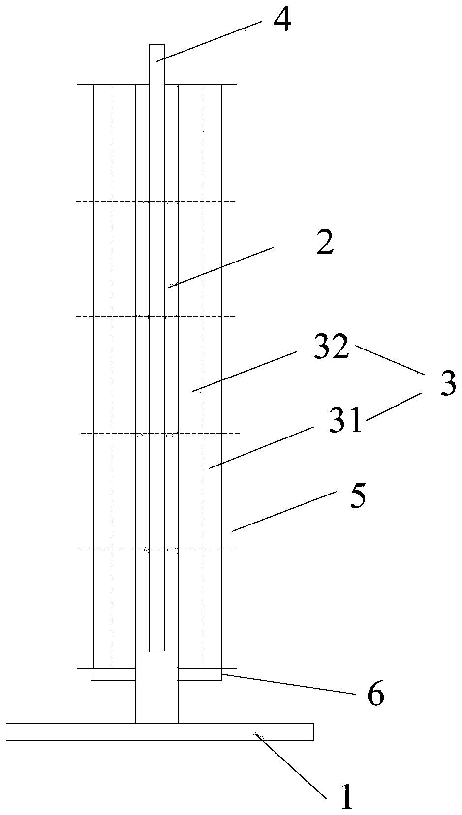
[0056] This embodiment provides a tube target desoldering device, the structure schematic diagram of the device is as follows figure 1 As shown, it includes a desoldering station and a heating assembly, the desoldering station includes a desoldering base plate 1 and a hollow tube 2 vertically fixed on the desoldering base plate 1, and the tube target 3 to be desoldered is set on the outside of the hollow tube 2; The heating assembly includes a heating rod 4 and at least one heating ring 5 , the heating rod 4 is arranged inside the hollow tube 2 , and the heating ring 5 is sleeved on the outside of the tube target 3 to be desoldered sequentially from bottom to top.

[0057] A circular ring 6 is provided on the outside of the lower part of the hollow tube 2 , and there is a gap between the circular ring 6 and the desoldering bottom plate 1 ; the bottom of the tube target 3 to be desoldered is in direct contact with the circular ring 6 .

[0058] The materials of the desoldering ...

Embodiment 2

[0064] This embodiment provides a tube target desoldering device, the device includes a desoldering station and a heating assembly, the desoldering station includes a desoldering base plate 1 and a hollow tube 2 vertically fixed on the desoldering base plate 1, to be The desoldering tube target 3 is set on the outside of the hollow tube 2; the heating assembly includes a heating rod 4 and at least one heating ring 5, the heating rod 4 is arranged inside the hollow tube 2, and the heating ring 5 is sequentially arranged from bottom to top Set on the outside of the pipe target 3 to be desoldered.

[0065] A circular ring 6 is provided on the outside of the lower part of the hollow tube 2 , and there is a gap between the circular ring 6 and the desoldering bottom plate 1 ; the bottom of the tube target 3 to be desoldered is in direct contact with the circular ring 6 .

[0066] The materials of the desoldering bottom plate 1 and the hollow tube 2 are stainless steel, and the mater...

Embodiment 3

[0072] This embodiment provides a tube target de-soldering device, the structure of the device refers to the structure in Example 1, the only difference is: the device does not include the ring 6, that is, the bottom of the tube target 3 to be de-soldered and the de-soldered The base plate 1 is in direct contact.


PUM


Abstract

The invention provides a tube target desoldering device and a using method thereof. The device comprises a desoldering table and a heating assembly, the desoldering comprises a desoldering bottom plate and a hollow tube vertically fixed on the desoldering bottom plate, the to-be-welded tube target is arranged on the outer side of the hollow tube in a sleeved mode; the heating assembly comprises a heating rod and at least one heating ring, the heating rod is arranged inside the hollow tube, and the heating ring is arranged on the outer side of the to-be-welded pipe target in sequence from bottom to top. According to the tube target desoldering device, the target material in the tube target and the back tube can be uniformly heated through the combination of a supporting structure and a heating assembly, when the welding flux is heated and molten, the separation of the target material and the back tube is realized, and the solder can be effectively recycled; the device is simple in structure and simple and convenient to use, the temperature is controllable in the desoldering process, the desoldering efficiency is high, and the device is especially suitable for off-welding separation of tubular target materials.

Description

technical field [0001] The invention belongs to the technical field of target recovery, and relates to a tube target de-soldering device and a use method thereof. Background technique [0002] Sputtering technology is one of the main processes for the preparation of film materials, and it is widely used in semiconductors, integrated circuits, flat-panel displays, and workpiece surface coatings. Among them, as an important component and material in the sputtering process, the sputtering target plays an increasingly important role, directly affecting the quality of the film material obtained after sputtering. [0003] The target assembly is usually composed of a target and a back plate. As a target with a tubular structure, the tube target is a commonly used target structure at present, and its outer surface is the ion bombardment surface. At this time Combined with it is the back tube, which is welded by putting the target material outside the back tube. The back tube materi...

Claims


Application Information

Patent Timeline
IPC IPC(8): B23K3/00B23K1/018C23C14/34
CPCB23K1/018B23K3/00C23C14/3407
Inventor 姚力军潘杰蒋云霞王学泽周伟君罗明浩
Owner KONFOONG MATERIALS INTERNATIONAL CO LTD
Why Eureka
Try Eureka