
A new type of magnetic separator and its application method

A magnetic separator, a new type of technology, applied in the field of magnetic separator, can solve the problems of high installation requirements, environmental impact, concentrate loss, etc., and achieve the effect of scientific and reasonable structure, safe and convenient use

Active Publication Date: 2020-06-23
HUNAN SHIZHUYUAN NON FERROUS METAL
View PDF7 Cites 0 Cited by
  • Summary
  • Abstract
  • Description
  • Claims
  • Application Information

AI Technical Summary

Problems solved by technology

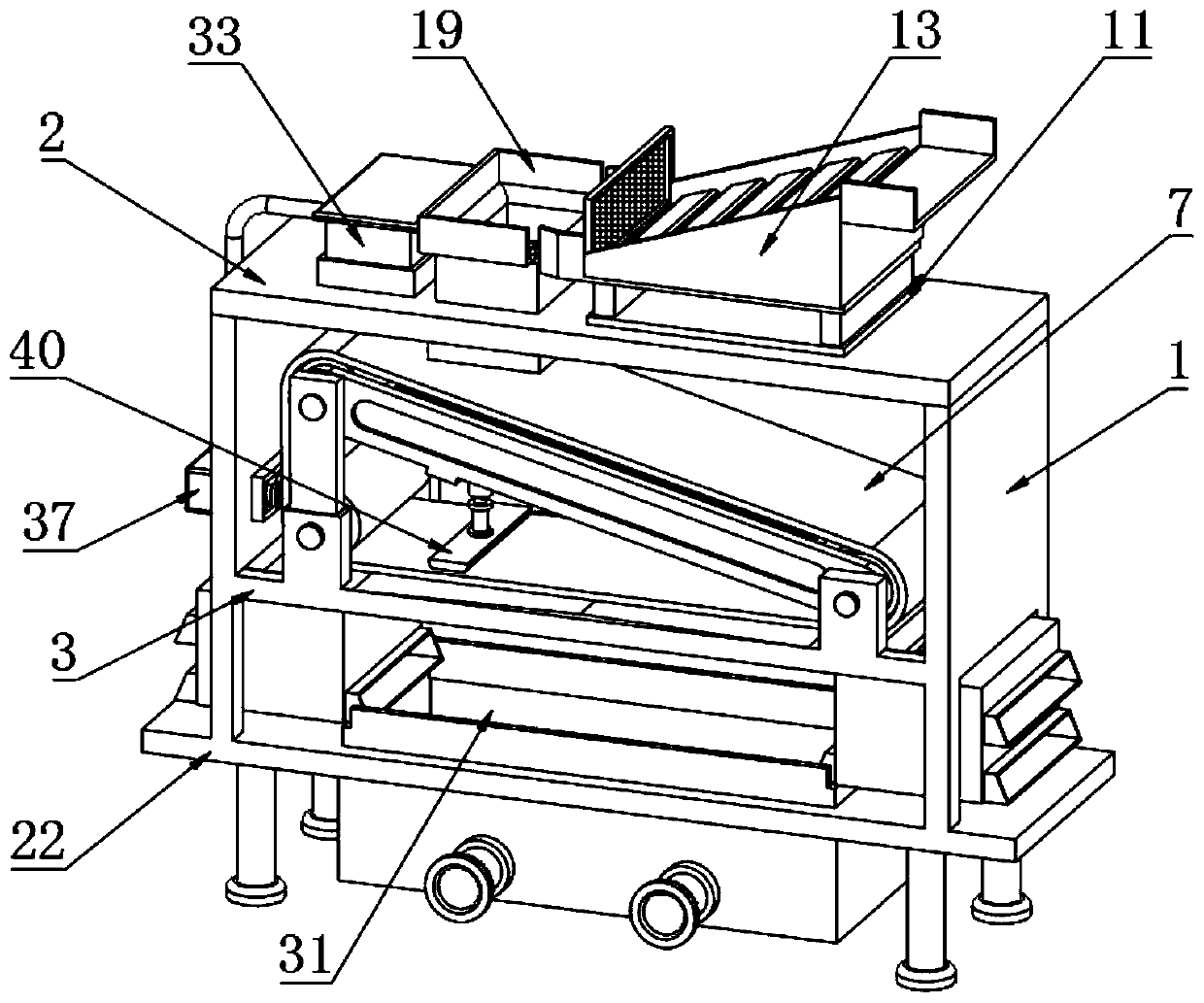
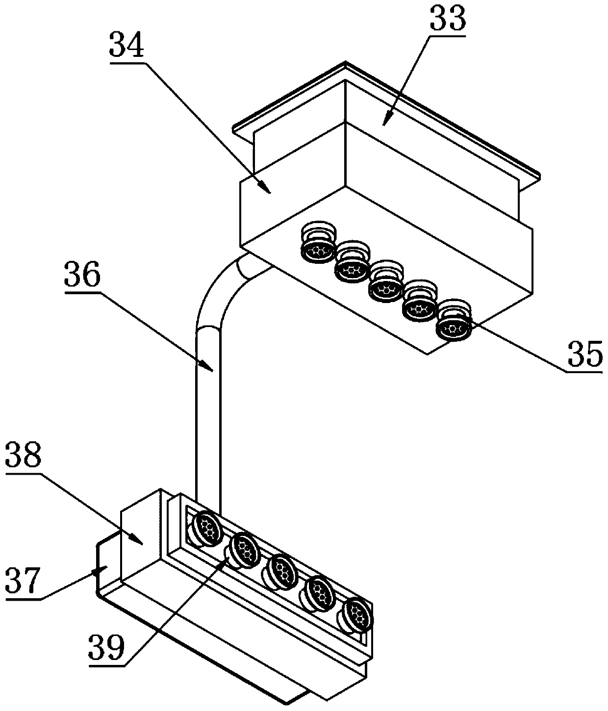
[0004] The present invention provides a new type of magnetic separator and its use method, which can effectively solve the problem that the magnetic separator in the prior art proposed in the above background technology usually processes the materials to be magnetically separated by a leveling device before the magnetic separation, and the leveling The feeding device is generally composed of a vibration motor and a crank-rocker mechanism. Due to the high installation requirements of the vibration motor and the crank-rocker mechanism when used in combination, it is not conducive to popularization and use, and the maintenance cost of the leveling device is relatively high. In addition, the existing magnetic separator lacks a mechanism for centralized collection of water resources after magnetic separation, so that when water resources are discharged directly after use, the tailings doped inside and the concentrate that has not been fully magnetically separated will be discharged directly. , not only is easy to affect the environment, but also causes the problem of loss of concentrate

Method used


Image

  • A new type of magnetic separator and its application method
  • A new type of magnetic separator and its application method
  • A new type of magnetic separator and its application method

Examples


Embodiment 1

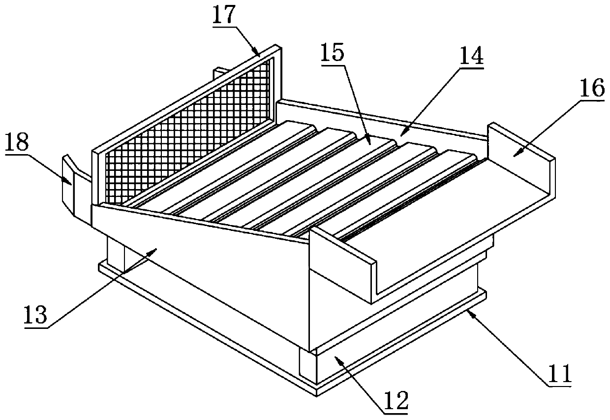
[0038] Embodiment 1: as Figure 1-8 As shown, the present invention provides a technical solution, a novel magnetic separator, comprising a mounting side plate 1, a top plate 2 is fixedly mounted on the top of the mounting side plate 1, a pressure-bearing bottom plate 3 is fixedly mounted on the bottom of the mounting side plate 1, and a bearing Mounting brackets 4 are symmetrically welded on both sides of the top of the pressure base plate 3. The top of the two mounting brackets 4 on one side of the top of the pressure base plate 3 is fixed with a support frame 5. The two mounting brackets located on both sides of the top of the pressure base plate 3 4 and the inner middle ends of the two supporting frames 5 are rotatably connected with a roller 6, and the outer sides of the three rollers 6 are all sleeved with a conveyor belt 7, and one end of the roller 6 is located on one side of the supporting frame 5 and is connected with a geared motor through a rotating shaft. And the ...


PUM


Abstract

The invention discloses a novel magnet separator and an application method. Magnetic slant plates are mounted on top ends of two support blocks, baffle plates are mounted on edge ends of both sides of the top of the magnetic slant plates, top surfaces of the magnetic slant plates are equidistantly equipped with magnetic strips at positions inside the two baffle plates, a feeding plate is connected with one end of the top of the magnetic slant plates, and a blocking screen is fixedly mounted at one end of the bottom of the magnetic slant plates. The structure is scientific and reasonable, the magnet separator is safe and convenient to use, through backing plates, the support blocks, the magnetic slant plates, the baffle plates, the magnetic strips, the feeding plate, the blocking screen and a guide plate, materials can be subjected to preliminary magnetic separation treatment before the materials are magnetically separated, simple mechanical combination is utilized to screen bulk iron blocks doped inside the materials, the bulk iron blocks are prevented from directly entering to damage a surface of a conveyor belt, and influence of the bulk iron blocks on the magnetic separation effect is further avoided.

Description

technical field [0001] The invention relates to the technical field of magnetic separators, in particular to a novel magnetic separator and its use method. Background technique [0002] Magnetic separator is a screening equipment used to remove iron powder in powdery granules. It is one of the most widely used and highly versatile models in the industry. It is suitable for the separation of substances with magnetic differences. At the same time, the magnetic separator Widely used in resource recovery, wood industry, mining industry, kiln industry, chemical, food and other factories, suitable for wet magnetic separation of magnetite, pyrrhotite, roasted ore, ilmenite and other materials with particle size below 3mm, and also It is used for iron removal operations of coal, non-metallic minerals, building materials and other materials; [0003] The magnetic separator in the prior art generally processes the materials to be magnetically separated by a leveling device before the...

Claims


Application Information

Patent Timeline
Patent Type & Authority Patents(China)
IPC IPC(8): B03C1/30B03C1/02B03C1/22B07B1/04B08B3/02B01D29/03
CPCB01D29/03B03C1/02B03C1/22B03C1/30B07B1/04B08B3/022
Inventor 周启明
Owner HUNAN SHIZHUYUAN NON FERROUS METAL
Learn More