Component assembly with fiber laser welded joint and method for this

A fiber laser, welding connection technology, applied in the field of component components, can solve problems such as weld failure

Pending Publication Date: 2019-09-27
ROBERT BOSCH GMBH
View PDF5 Cites 0 Cited by
  • Summary
  • Abstract
  • Description
  • Claims
  • Application Information

AI Technical Summary

Problems solved by technology

Now research has found that due to the over 800×10 5 Extremely high pressures in the Pa range, under vibration loads, as in the case of internal combustion engines for vehicles, can lead to failure of the weld due to overloading in the case of currently used welded connections

Method used


Image

  • Component assembly with fiber laser welded joint and method for this
  • Component assembly with fiber laser welded joint and method for this
  • Component assembly with fiber laser welded joint and method for this

Examples


Embodiment Construction

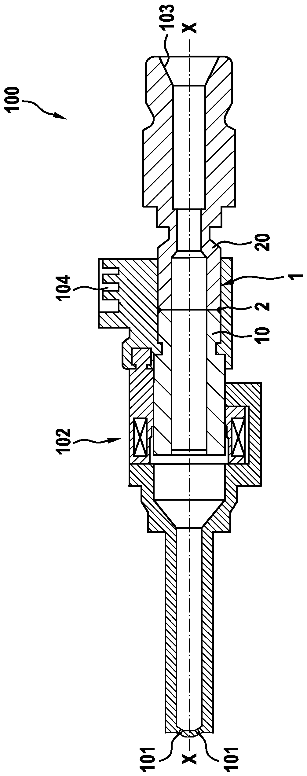
[0036] Refer below figure 1 and 2 A component assembly 1 and a method for producing a fiber laser welding connection are described in detail according to a preferred embodiment.

[0037] figure 1 An injector 100 with a longitudinal axis X-X is shown schematically, comprising a component assembly 1 according to the invention. The component assembly 1 here comprises a first component 10 and a second component 20 .

[0038] In this exemplary embodiment, the first component 10 is the inner pole 10 of the injector 100 and the second component 20 is the connection sleeve, by means of which the hydraulic connection of the injector 100 takes place.

[0039] The injector 100 comprises an injection opening 101 and an electromagnetic actuator 102 , wherein the first component 10 is here a part of the electromagnetic actuator 102 . Furthermore, a hydraulic connection 103 and an electrical connection 104 are shown.

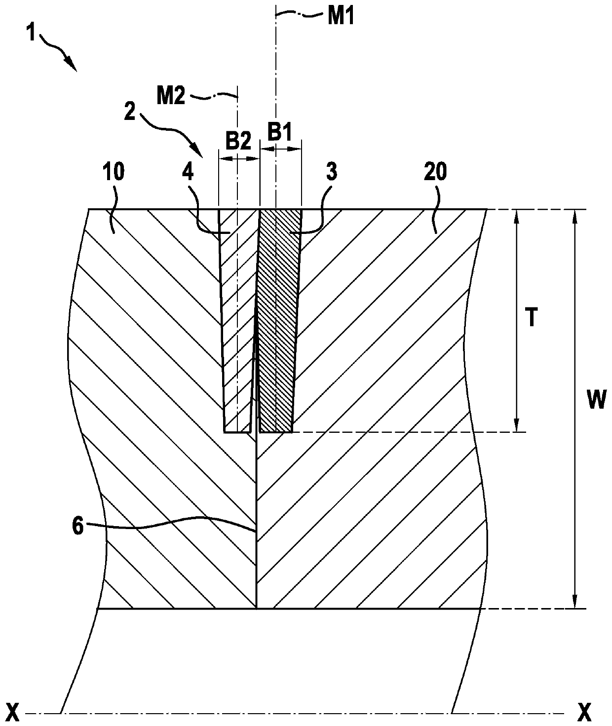
[0040] figure 2 The component assembly 1 is shown in detail. In t...


PUM

PropertyMeasurementUnit
diameteraaaaaaaaaa

Abstract

The invention relates to a component assembly, comprising a first component (10), a second component (20), and an optical fiber laser welding connection (2) disposed between the first component (10) and the second component (20), which can connect the first component to the second component at a bonding gap (6). The optical fiber laser welding connection (2) at least includes a first welding seam (3) and a second welding seam (4), which are arranged in parallel in a manner of mutually contacting. The invention also relates to a method for manufacturing the optical fiber laser welding connection.

Description

technical field [0001] The invention relates to a component assembly with a fiber optic laser welding connection, an injector, in particular a fuel injector with such a component assembly, and a method for producing a fiber optic laser welding connection. Background technique [0002] Various configurations of welded connections between two components are known from the prior art. For example, in the manufacture of fuel injectors, two components, namely the inner pole and the connection sleeve, are connected to one another by means of a welded connection. Here, a single weld seam is produced with the aid of a disk laser. As the environmental protection standards of internal combustion engines continue to increase, the injection pressure of diesel internal combustion engines and gasoline internal combustion engines is also continuously increasing. Now research has found that due to the over 800×10 5 Extremely high pressures in the Pa range, under vibration loads, as in the...

Claims


Application Information

Patent Timeline
Patent Type & Authority Applications(China)
IPC IPC(8): B23K26/24B23K26/70B23K37/04
CPCB23K26/24B23K26/702B23K37/0435B23K26/242B23K26/282B23K26/32B23K26/0823B23K26/103B23K2101/006B23K2101/06F02B23/0645B23K2101/04
Inventor J·沙梅尔O·库尔巴克C·辛凯尔M·贝林格A·博尔曼
Owner ROBERT BOSCH GMBH
Why Eureka
Try Eureka