Polishing machine for polishing pot body

A polishing machine and pot body technology, which is applied in the field of polishing machines, can solve the problems of low polishing efficiency, time-consuming and laborious, etc., and achieve the effects of saving manpower and material resources, promoting high efficiency, and improving polishing and grinding efficiency

Pending Publication Date: 2019-09-27
四川金诚祥厨具有限公司
View PDF1 Cites 0 Cited by
  • Summary
  • Abstract
  • Description
  • Claims
  • Application Information

AI Technical Summary

Problems solved by technology

[0003] In the production and preparation process of the pot, the pot body needs to be polished, and in the existing pot body polishing equipment, such as a polishing device for the outer surface of an iron pot disclosed in Chinese Patent Publication No. CN208342522U, it includes a fixed plate surface and a polishing plate , one side of the fixed plate rotates symmetrically at both ends and a drive shaft is provided, one end of the drive shaft penetrates the fixed plate and is fixedly installed with a rotating connecting rod, and the side of the rotating connecting rod far away from the driving shaft is fixedly installed with a first ball joint; The internal rotation of the fixed plate is equipped with a drive shaft, which can be connected to an external motor to make it rotate, thereby driving the rotation of the rotating connecting rod, and the rotating connecting rod drives the polishing plate to move up and down, and finally achieves a convenient, adjustable and handleable iron pot Although the polishing device can realize the polishing of the surface of the pot body, the user needs to control the polishing device all the time during the polishing process, which is time-consuming and laborious, and the polishing efficiency is low.

Method used


Image

  • Polishing machine for polishing pot body
  • Polishing machine for polishing pot body

Examples


Embodiment Construction

[0019] The technical solution of the present invention will be further described in detail below in conjunction with the accompanying drawings, but the protection scope of the present invention is not limited to the following description.

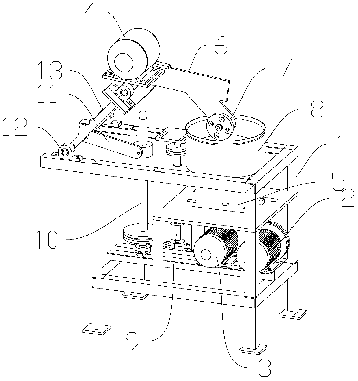
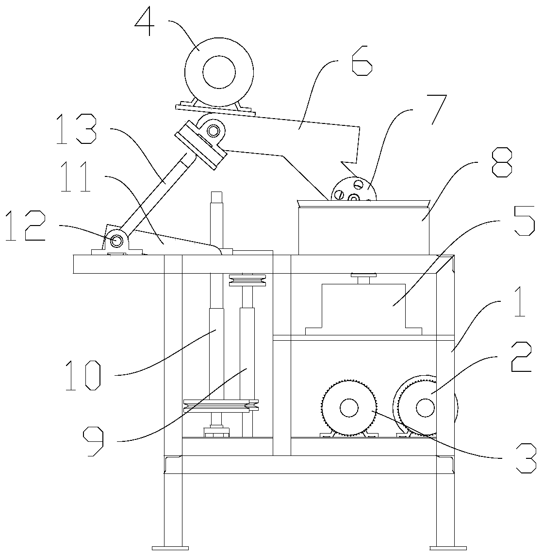
[0020] Such as figure 1 with figure 2 As shown, a polishing machine for polishing a pot body includes a frame 1, a first drive motor 2, a second drive motor 3, a third drive motor 4, a reducer 5, a rotating arm 6, a grinding wheel 7, and a support cylinder 8. The transmission shaft 9 and the lifting screw 10, the support cylinder 8 is arranged on the top of the frame 1 for placing the pot body, the reducer 5 is arranged under the support cylinder 8, the first drive motor 2, The second driving motor 3 is respectively arranged in the frame 1, and the first driving motor 2 controls the rotation of the pot body in the support cylinder 6 through the reducer 5, and the second driving motor 3 is connected with the transmission shaft 9 by a belt,...


PUM


Abstract

The invention discloses a polishing machine for polishing a pot body, comprising a rack, a first driving motor, a second driving motor, a third driving motor, a speed reducer, a rotating arm, a grinding wheel, a supporting cylinder, a transmission shaft and a lifting screw rod, wherein the supporting cylinder is arranged at the top of the rack for placing the pot body; the speed reducer is arranged below the supporting cylinder; the first driving motor and the second driving motor are respectively arranged in the rack; the first driving motor controls the pot body in the supporting cylinder to rotate by the speed reducer, and the second driving motor is connected with the transmission shaft through a belt; the transmission shaft is connected to the lifting screw rod through the belt. The polishing machine polishes the pot body by the surface fitting displacement of the grinding wheel and the pot body, and a user does not need to control the equipment all the time in the polishing process, so that the user can simultaneously operate a plurality of polishing machines for polishing, saving manpower and material resources. The polishing machine improves the polishing efficiency of the pot body and is of great significance for promoting the high efficiency and high quality production of the pot body.

Description

technical field [0001] The invention relates to the technical field of mechanical processing equipment, in particular to a polishing machine for polishing a pot body. Background technique [0002] A pot is a cooking utensil, which can be used for cooking, boiling, frying, frying, frying and other cooked food. Pot has a long history of use and is an indispensable tool in Chinese cooking, which can supplement trace amounts of iron in the human body. Polishing machines, also known as grinders, are often used for mechanical grinding, polishing and waxing. Its working principle is: the motor drives the sponge or wool polishing disc installed on the polishing machine to rotate at high speed. Due to the joint action of the polishing disc and the polishing agent and friction with the surface to be polished, it can achieve the effect of removing paint surface pollution, oxide layer and shallow marks. Purpose. The speed of the polishing disc is generally 1500-3000r / min, mostly step...

Claims


Application Information

Patent Timeline
Patent Type & Authority Applications(China)
IPC IPC(8): B24B29/04B24B47/22B24B47/12
CPCB24B29/04B24B47/12B24B47/22
Inventor 杨杜洋佘伟
Owner 四川金诚祥厨具有限公司
Why Eureka
Try Eureka