Integrated piezoelectric vibration resistance reducer capable of being embedded in wall face

A piezoelectric vibrator and piezoelectric vibration technology, applied in the field of piezoelectric vibration drag reduction devices and integrated piezoelectric vibration drag reducers, can solve the problems of complex structure, large space occupation, and poor versatility of drag reducers, and achieve Novel design, reduced resistance, simple and compact structure

Active Publication Date: 2019-09-27
HARBIN INST OF TECH
View PDF20 Cites 1 Cited by
  • Summary
  • Abstract
  • Description
  • Claims
  • Application Information

AI Technical Summary

Problems solved by technology

[0003] The purpose of the present invention is to provide an integrated piezoelectric vibration damper that can be embedded in the wa...

Method used


Image

  • Integrated piezoelectric vibration resistance reducer capable of being embedded in wall face
  • Integrated piezoelectric vibration resistance reducer capable of being embedded in wall face
  • Integrated piezoelectric vibration resistance reducer capable of being embedded in wall face

Examples


Embodiment 1

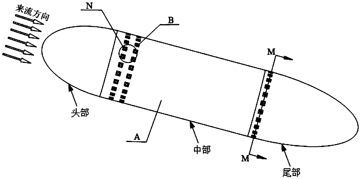
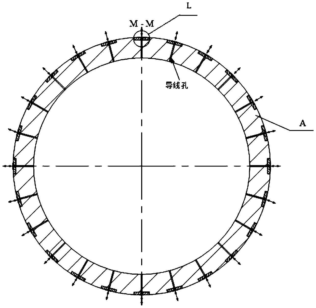
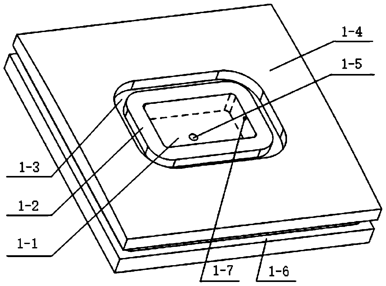
[0040] Embodiment 1: see Figure 1-4 , Figure 11-12 , an integrated piezoelectric vibration damper that can be embedded in the wall described in this embodiment includes three rows of piezoelectric vibration dampers B, and the piezoelectric vibration dampers B are embedded on the outer wall of the underwater vehicle A , the underwater vehicle A includes a head, a tail and a middle part, the head and the tail are conical, and the middle part is cylindrical, and the piezoelectric vibration damper B is specifically embedded in the middle part of the underwater vehicle A and the tail, the piezoelectric vibration damper B comprises a damper cavity 1 and a piezoelectric vibrator, and the piezoelectric vibrator comprises a copper sheet 2, a piezoelectric sheet 3, and a wire 4; the drag reducer cavity The body 1 is embedded into the outer wall of the underwater vehicle A, and the two are sealed and installed through the sealing ring II7; the copper sheet 2 is placed in the middle of...

Embodiment 2

[0043] Embodiment 2: combine below figure 1 , 2 , 5-7, and 11-12 illustrate this embodiment. The difference between this embodiment and Embodiment 1 is that the underwater vehicle A uses a cantilever type drag reducer when it works in a shallow water area with low pressure. The piezoelectric sheet 3 is pasted on the middle position of the inner surface of the copper sheet 2, the left end of the inner surface of the copper sheet 2 is glued and fixed to the reference plane 1-2, and the diaphragm 9 is pasted on the rest of the inner surface of the copper sheet 2, and the film The lower surface of the sheet 9 is glued to the horizontal plane 1-8 of the drag reducer cavity 1, and the horizontal plane 1-8 is a plane milled downward from the reference plane 1-2. The diaphragm 9 plays a role of connection and sealing. The piezoelectric strain constant matrix is ​​d 31 When the piezoelectric sheet 3 is in the working mode, use its contraction and expansion to make the right end of th...

Embodiment 3

[0044] Embodiment 3: combine below figure 1 , 2 , 3, 8, 11-12 illustrate this embodiment, the difference between this embodiment and Embodiments 1 and 2 is that the piezoelectric sheet 3 can be replaced by a piezoelectric stack I5 in the piezoelectric vibration damper B, The piezoelectric stack I5 is located right below the copper sheet 2 . When the internal space of the underwater vehicle A is relatively large, the piezoelectric stack I5 with longitudinal vibration is adopted, and the piezoelectric stack I5 of the longitudinal vibration type adopts a piezoelectric strain constant matrix of d 33 The working mode, that is, polarization along the thickness direction, mainly produces displacement changes in the thickness direction. When the external excitation drives the piezoelectric stack 5, its vibration direction is perpendicular to the copper sheet 2, so that the copper sheet 2 can obtain a higher Large amplitude, increased drag reduction rate.


PUM


Abstract

The invention discloses an integrated piezoelectric vibration resistance reducer capable of being embedded in the wall face, and belongs to the technical field of fluid vibration resistance reducing. The problems that an existing resistance reducer is complex in structure, large in occupied space, difficult in control and poor in universality are solved. The integrated piezoelectric vibration resistance reducer is technically characterized in that the head and the tail of an underwater vehicle are in a conical shape, the middle portion is in a cylindrical shape, piezoelectric vibration resistance reducer bodies are specifically embedded in the middle portion and the tail of the underwater vehicle and each comprises a resistance reducer cavity and a piezoelectric vibrator; the piezoelectric vibrator of each piezoelectric vibration resistance reducer body comprises a copper sheet, a piezoelectric plate or a piezoelectric stack I or a piezoelectric stack II and a wire, wherein the copper sheet is placed in the middle of the corresponding resistance reducer cavity, the copper sheet and the corresponding resistance reducer cavity are installed in a sealed manner, and the top end of the piezoelectric plate or the piezoelectric stack I or the piezoelectric stack II is in glue joint with the copper sheet and located below the copper sheet; and an auxiliary hole is formed in each resistance reducer cavity and used for guiding-out of the wire of the corresponding piezoelectric vibrator. The integrated piezoelectric vibration resistance reducer is used for reducing the fluid contact wall face friction resistance and delaying boundary layer separation during sailing of the underwater vehicle, and pressure difference resistance is reduced.

Description

technical field [0001] The invention relates to a piezoelectric vibration drag reduction device, in particular to an integrated piezoelectric vibration drag reducer that can be embedded in a wall, and belongs to the technical field of fluid vibration drag reduction. Background technique [0002] When an underwater vehicle sails, the walls in contact with the fluid tend to generate resistance, and drag reduction has also become a key issue in the design of underwater vehicles. At present, most drag reducers are aimed at wings in the air, and there are very few drag reducers that can be used for underwater ships and underwater vehicles; existing underwater drag reducers have complex structures, such as: Chinese Patent Publication No. It is CN108674575A, which relates to a fluid drag reduction device. A drag reduction belt with openings is arranged around the hull or at the bottom, and an exhaust pipe is placed in the hole. The realization of drag reduction requires a gas compr...

Claims


Application Information

Patent Timeline
IPC IPC(8): B63B1/36B63B1/38B63B1/32G06F17/50
CPCB63B1/36B63B1/38B63B1/32G06F30/15G06F30/20Y02T70/10Y02T90/00
Inventor 张露单小彪谢涛
Owner HARBIN INST OF TECH
Why Eureka
Try Eureka