Drying device used in tobacco industry

A drying device and industry technology, applied in the direction of tobacco drying, drying, drying machine, etc., can solve the problems of energy waste, unfavorable environmental protection, increase energy consumption, etc., achieve uniform heating, reduce waste, and benefit the environment the protective effect of

Active Publication Date: 2019-09-27
SHANDONG QINGDAO TOBACCO
View PDF8 Cites 3 Cited by
  • Summary
  • Abstract
  • Description
  • Claims
  • Application Information

AI Technical Summary

Problems solved by technology

[0003] After searching, the Chinese utility model patent with the application number 201820087642.3 discloses a tobacco dryer, and specifically discloses a support frame, a drying cylinder is arranged on the support frame, and a feeding port is provided on the top of the drying cylinder. There is a feeding cover on the feeding port, a stirring device and a heating device on the drying cylinder, the feeding port is arranged along the length direction of the drying drum, an empty shell interlayer is provided on one side of the feeding port, and a hollow shell interlayer is installed in the empty shell interlayer. The feed cover is provided with grooves on the other side of the feed port, magnetic substances are provided in the grooves, magnets are provided on the feed cover, chutes are provided on both sides of the feed port, and both sides of the feed cover are provided with There are sliders, a buckle ring is provided on the feeding cover, an air outlet is provided on the top of the drying cylinder, a filter is provided on the air outlet, an air suction device is provided on one side of the drying cylinder, and a suction device is provided on the inner wall of the drying cylinder. Humidity sensor, the outer wall of the drying cylinder is equipped with a humidity display, and the humidity sensor is electrically connected to the humidity display. After research, it is found that although it can achieve good control and mastery of tobacco drying and high work efficiency, it still exists. The following defects: the heat generated by the hot air blower in the heating device is transferred to the drying cylinder. After the tobacco in the drying cylinder is heated and dried, the heat is discharged to the outside of the drying cylinder under the action of the suction device, and the heat is not utilized. Direct discharge will cause energy waste and increase energy consumption, which is not conducive to environmental protection

Method used


Image

  • Drying device used in tobacco industry
  • Drying device used in tobacco industry
  • Drying device used in tobacco industry

Examples


Embodiment 1

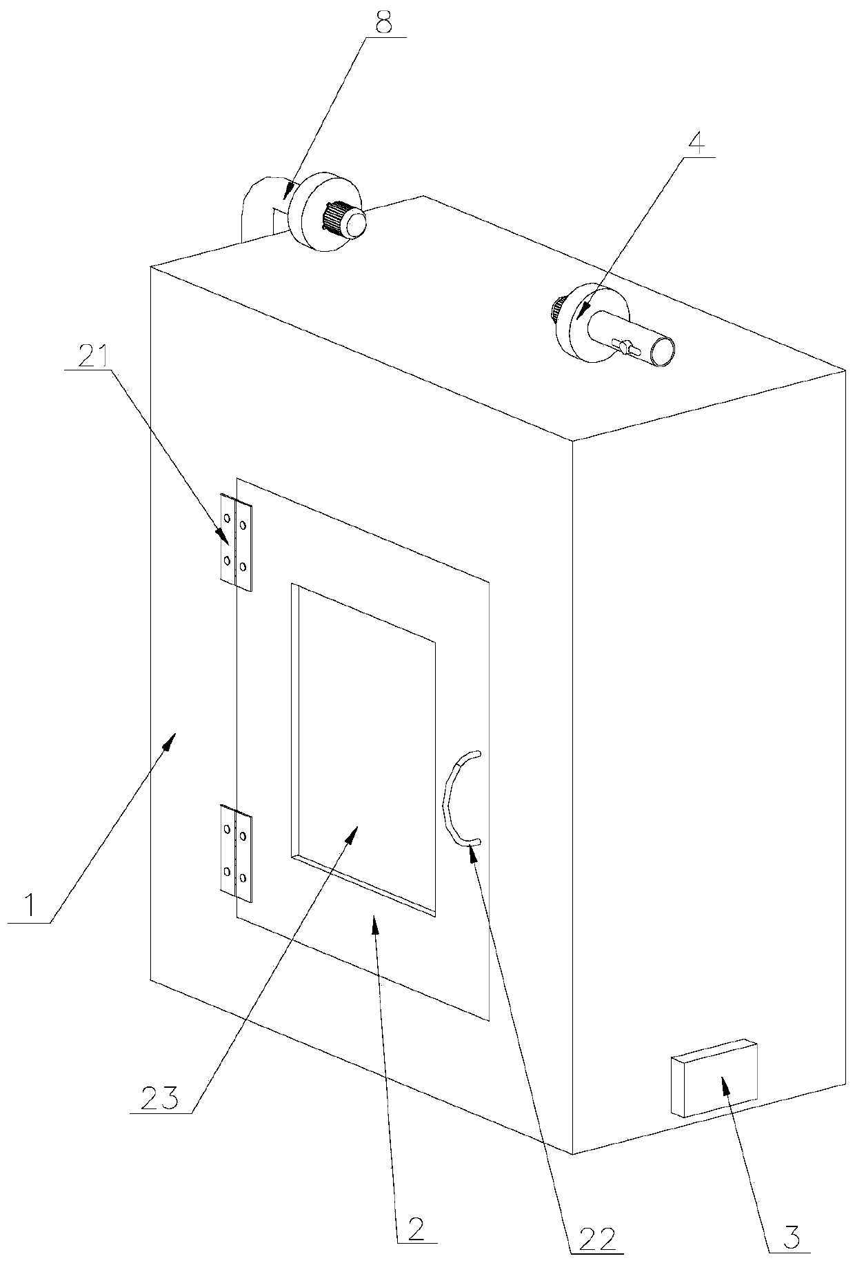
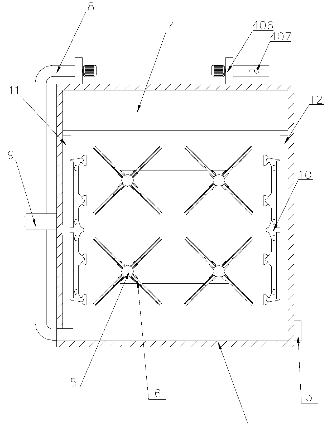
[0048] Such as Figure 1-9 As shown, a drying device for the tobacco industry includes a working box 1, a movable door 2, a heating device 4, a power unit 5, a drying rack 6, a fixing device 7, and a gas circulation device 8. The working box 1 There is a dodge door 2 on the top, and a handle 22 is provided on the dodge door 2. The dodge door 2 and the working box body 1 are hinged through a hinge 21 to facilitate the opening and closing of the dodge door 2. Put the tobacco to be dried into the To the inside of the working box 1 for drying, the top of the working box 1 is provided with a heating device 4, and the inner wall of one side of the working box 1 is provided with a temperature sensor 11, and the temperature sensor 11 adopts a commercially available mature product For example, the model 00PT100 platinum resistance temperature sensor produced by Shanghai Nijing Electronic Technology Co., Ltd. senses the temperature inside the working box 1 through the temperature sensor...

Embodiment 2

[0060] Such as Figure 10-11 As shown, the difference from Embodiment 1 is that the fixing device 7 includes a vertical plate 706, a first screw 707, a movable block 709, a second screw 710, a first round block 711, a second round block 714, and a sleeve 715 , fixed legs 716, the vertical plate 706 is arranged on both sides of the end of the placement frame 602, between the two placement frames 602, the middle part of the vertical plate 706 is provided with a through hole 708, so that the gas passes through the vertical plate 706 and the placement frame 602 Tobacco contact, the upper and lower sides of the vertical plate 706 are symmetrically provided with a number of first screw rods 707, the vertical plate 706 is provided with threaded holes that cooperate with the first screw rods 707, and the end of the first screw rod 707 is provided with a first round Block 711, the inner side of the vertical plate 706 is provided with a movable block 709, the movable block 709 is locate...

Embodiment 3

[0062] Such as Figure 10 , Figure 11 As shown, the difference from Embodiment 1 is that the fixing device includes a vertical plate 706, a first screw rod 707, a movable block 709, a first round block 711, a fixed leg 716, a pull rod 717, a spring 718, and the vertical plate 706 Set on both sides of the end of the rack 602, between the two racks 602 and the middle of the vertical plate 706, a through hole 708 is provided to facilitate the gas to pass through the vertical plate 706 and contact the tobacco on the rack 602. The vertical plate 706 is up and down Both sides are symmetrically provided with several first screw rods 707, and the vertical plate 706 is provided with threaded holes cooperating with the first screw rods 707. Movable block 709, the movable block 709 and the first screw rod 707 are located on the same axis, the first round block 711 is arranged in the cavity 712 inside the movable block 709, by rotating the first screw rod 707, the first round block 711 ...


PUM


Abstract

The invention discloses a drying device used in tobacco industry. The drying device comprises a working box body, a movable door, a heating device and a drying frame, wherein the movable door is arranged on the working box body, a handle is arranged on the movable door, the movable door is hinged to the working box body through a hinge, the heating device is arranged at the upper part inside the working box body, and the drying frame is arranged below the heating device. The drying device provided by the invention can be used for full drying to cigarettes and tobacco, so that cigarettes and tobacco is heated uniformly, the quality of the finished cigarettes and tobacco is ensured, gas produced after tobacco drying can be recycled, energy waste is reduced, and environment protection is facilitated.

Description

technical field [0001] The invention belongs to the technical field of tobacco processing, in particular to a drying device for the tobacco industry. Background technique [0002] Tobacco is a plant of the genus Nicotiana in the family Solanaceae, an annual or limited perennial herb, all covered with glandular hairs; the root is thick, the stem is 0.7-2 meters high, and the base is slightly lignified; the leaves are oblong-lanceolate, lanceolate, oblong or oval , apex acuminate, base tapering until the stem becomes ear-shaped and semi-embracing; inflorescence terminal, paniculate, many flowers; pedicel 5-20 mm long; capsule ovate or oblong, about equal to persistent calyx in length, The seeds are round or broadly oblong, about 0.5 mm in diameter, brown; they can be used as raw materials in the tobacco industry; the whole plant can also be used as pesticides and insecticides; they can also be used medicinally for anesthesia, sweating, sedation and emetics. [0003] After sea...

Claims


Application Information

Patent Timeline
Patent Type & Authority Applications(China)
IPC IPC(8): F26B3/28F26B11/18F26B21/02F26B21/10F26B25/12F26B25/18
CPCF26B3/28F26B11/18F26B21/02F26B21/10F26B25/12F26B25/18F26B2200/22
Inventor 许桂凤崔文超孙坤徐德志纪春波蔡继军毕莹苗升起
Owner SHANDONG QINGDAO TOBACCO
Why Eureka
Try Eureka