A rotating electromechanical experimental device with variable system parameters

A technology of system parameters and experimental devices, applied in teaching models, instruments, educational appliances, etc., can solve the problems of single model, fixed, unable to change the structural parameters of the experimental bench, etc., to facilitate construction, ensure transmission ratio, and facilitate observation and understanding. Effect

Inactive Publication Date: 2021-07-27
陕西巍晟机电设备有限公司
View PDF7 Cites 0 Cited by
  • Summary
  • Abstract
  • Description
  • Claims
  • Application Information

AI Technical Summary

Problems solved by technology

However, this type of test bench cannot change the structural parameters of the test bench itself, and the established model is single and fixed.

Method used


Image

  • A rotating electromechanical experimental device with variable system parameters
  • A rotating electromechanical experimental device with variable system parameters

Examples


Embodiment 1

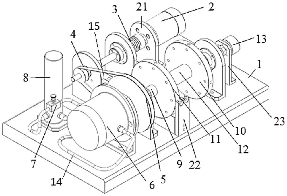
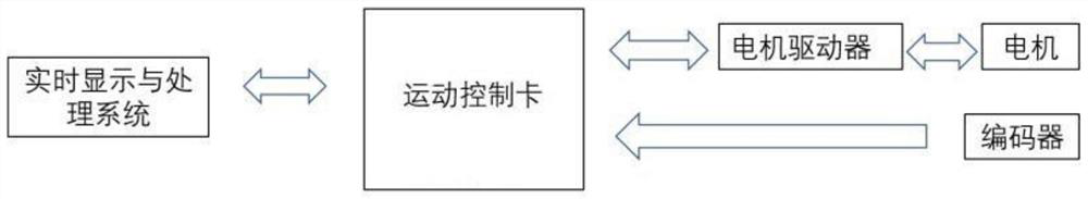
[0032] Such as figure 1 A rotary electromechanical experimental device with variable system parameters is shown, including a base 1 and a motor 2 installed on the base 1, a drive shaft 3, a deceleration system, and a rotating shaft 12; the deceleration system includes a driving wheel 4, Driven wheel 5 and driving belt 15. The motor 2 is connected with the motor driver, the motor driver is connected with the motion control card, and the motion control card is connected with the computer and the encoder 13.

[0033] The axes of the drive shaft system 3 and the rotation shaft system 12 are all parallel to the base 1, the motor 2 is installed on the motor mount 21 fixedly connected to the base 1, and is connected with one end of the drive shaft system 3, the preferred direct drive motor of the motor 2, The other end of the drive shaft 3 series is equipped with a driving wheel 4, which can be provided with some bearings on the driving shaft system 3 according to actual needs, and ...

Embodiment 2

[0035] The reduction system adopts a synchronous belt drive, the driving wheel 4 and the driven wheel 5 adopt transmission gears, and the transmission belt 15 adopts a synchronous belt. The central aperture of the free turntable 11 is larger than the shaft diameter of the rotating shaft system 12, and can move freely within a certain length range. The end face of the free turntable 11 is provided with a number of through holes. The free turntable 11 adopts a two-lobed structure. After the splicing sleeve is set on the rotating shaft system 12, the free turntable 11 and the fixed turntable 10 are connected into a whole through connecting parts such as screws, bolts and nuts, so that the free turntable 11 can be fixed with the fixed turntable 10 and rotate together with the drive shaft 3; When not in use, the free rotating disc 11 of the two-lobed formula is pulled down. All the other components and connections are the same as in Embodiment 1.

Embodiment 3

[0037] The reduction system adopts a gearbox, the output end of the driving shaft system 3 is connected to the input end of the gearbox, and the input end of the rotating shaft system 12 is connected to the output end of the gearbox. Different reduction ratios can be realized by selecting gearboxes with different reduction ratios. . All the other components and connections are the same as in Embodiment 1.


PUM


Abstract

The invention discloses a rotary electromechanical experimental device with variable system parameters, which belongs to the technical field of experimental equipment. Including the base and the motor, drive shaft, deceleration system, and rotation shaft set on the base; by setting the drive shaft and rotation shaft, integrating the deceleration system, damping system and fixed turntable that can adjust the moment of inertia, the motor drives the drive shaft After the system rotates, the encoder is used to measure the rotational speed of the rotating shaft system by changing the reduction ratio, damping and moment of inertia. By controlling various parameters, the transfer function between various parameters and the rotational speed of the device is studied. The structure design of the device is reasonable, each system is composed of typical mechanical parts, and the operation of each system can be observed intuitively, which is easy to observe and understand. Establish a variety of experimental models to study its transfer function, and can also perform algorithmic control.

Description

technical field [0001] The invention belongs to the technical field of experimental equipment, and in particular relates to a rotary electromechanical experimental device with variable system parameters. Background technique [0002] In the experiments of related courses such as the principle of automation control and the basics of mechanical control engineering, it is generally necessary to use a test bench to cooperate with the explanation of the basic characteristics and control effects of the control system, so that students have an intuitive and deep understanding of the course knowledge and content. There are currently two types of test benches for control systems: 1. Electric control simulation test benches, which simulate first-order and second-order systems with different parameters through capacitors, resistors, amplifiers, etc. Although this type of test bench is more intuitive , but it is far from the actual mechanical objects; 2. Inverted pendulum, club system a...

Claims


Application Information

Patent Timeline
Patent Type & Authority Patents(China)
IPC IPC(8): G09B25/02
CPCG09B25/02
Inventor 王欢杨林
Owner 陕西巍晟机电设备有限公司
Why Eureka
Try Eureka