Cyclone-type cycling filtration gas-water separation device for fuel cell system

A technology of gas-water separation device and fuel cell system, which is applied in the direction of fuel cells, electrical components, circuits, etc., and can solve the problems of low-temperature cold start failure of fuel cell engines, affecting the working performance of fuel cell stacks, and the limited guiding effect of guide vanes and other problems, to achieve the effect of improving the efficiency of gas-water separation, wide application range, and low processing difficulty

Pending Publication Date: 2019-09-27
武汉泰歌氢能汽车有限公司
0 Cites 5 Cited by

AI-Extracted Technical Summary

Problems solved by technology

[0003] Existing air-water separators for vehicles mainly use filter elements to filter, referring to the air-water separators used in air compressors, the top of the filter element is equipped with axial guide vanes arranged along the outer diameter of the filter element, but the guide vanes of this type The flow effect is very limited and cannot form a sufficient swirling air flow to promote the separation of liquid droplets from the gas
And under different working conditions, when the gas flow rate is cha...

Method used

Cyclone circulation filter part 3 is installed directly below loam cake 1, and is positioned at tank body 2, and cyclone circulation filter part 3 can be installed in the below of loam cake 1 by bolt, with reference to Fig. 2, cyclone circulation filter part 3 comprises Some guide vanes 31, air outlets 32, some overflow ports 33 and beam tubes 34, the inside of the beam tubes 34 are hollow structures, and the shape is cylindrical, and the air outlets 32 are integrally connected to the upper end of the beam tubes 34, and the air outlets The shape of 32 is cylindrical, and the diameter of air outlet 32 ​​is less than the diameter of beam tube 34, and the inside of air outlet 32 ​​and beam tube 34 is connected to form air outlet channel, and the direction of air outlet 32 ​​is perpendicular to the direction of outlet 5, and guide vane 31 is integrally connected to the upper end of the beam tube 34, and the guide vanes 31 are evenly arranged in a spiral shape along the outside of the air outlet 32, and one end of the guide vanes 31 is connected to the upper end side wall of the beam tube 34, and the guide vanes 31 The other end gathers along the air outlet 32, the height of the guide vane 31 is slightly less than or equal to the height of the air outlet 32, and...

Abstract

The invention provides a cyclone-type cycling filtration gas-water separation device for a fuel cell system, which comprises a shell and a cyclone cycling filtration part, wherein the shell comprises an upper cover and a can body connected to the upper cover; the upper end of the upper cover is provided with an inlet; the side wall of the upper cover is provided with an outlet; the inner part of the can body has a hollow structure; the can body is communicated with the inlet and the outlet; the lower end of the can body is provided with a drain port; the cyclone cycling filtration part is mounted below the upper cover, and comprises a plurality of guide vanes, an air outlet, a plurality of overflow ports and a beam tube ; the inside of the beam tube is a hollow structure; the air outlet is connected to the upper end of the beam tube and is communicated with the inner part of the beam tube; the guide vanes are uniformly arranged at the upper end of the beam tube along the outer side of the air outlet in a spiral shape; and the overflow ports are opened at the upper end of the beam tube and are arranged along the side wall of the upper end of the beam tube. The gas-water separation efficiency is high, and the operation is safe and reliable.

Application Domain

Technology Topic

Beam tubeEngineering +4

Image

  • Cyclone-type cycling filtration gas-water separation device for fuel cell system
  • Cyclone-type cycling filtration gas-water separation device for fuel cell system

Examples

  • Experimental program(1)

Example Embodiment

[0019] In order to make the purpose, technical solution and advantages of the present invention clearer, the embodiments of the present invention will be further described below in conjunction with the accompanying drawings.
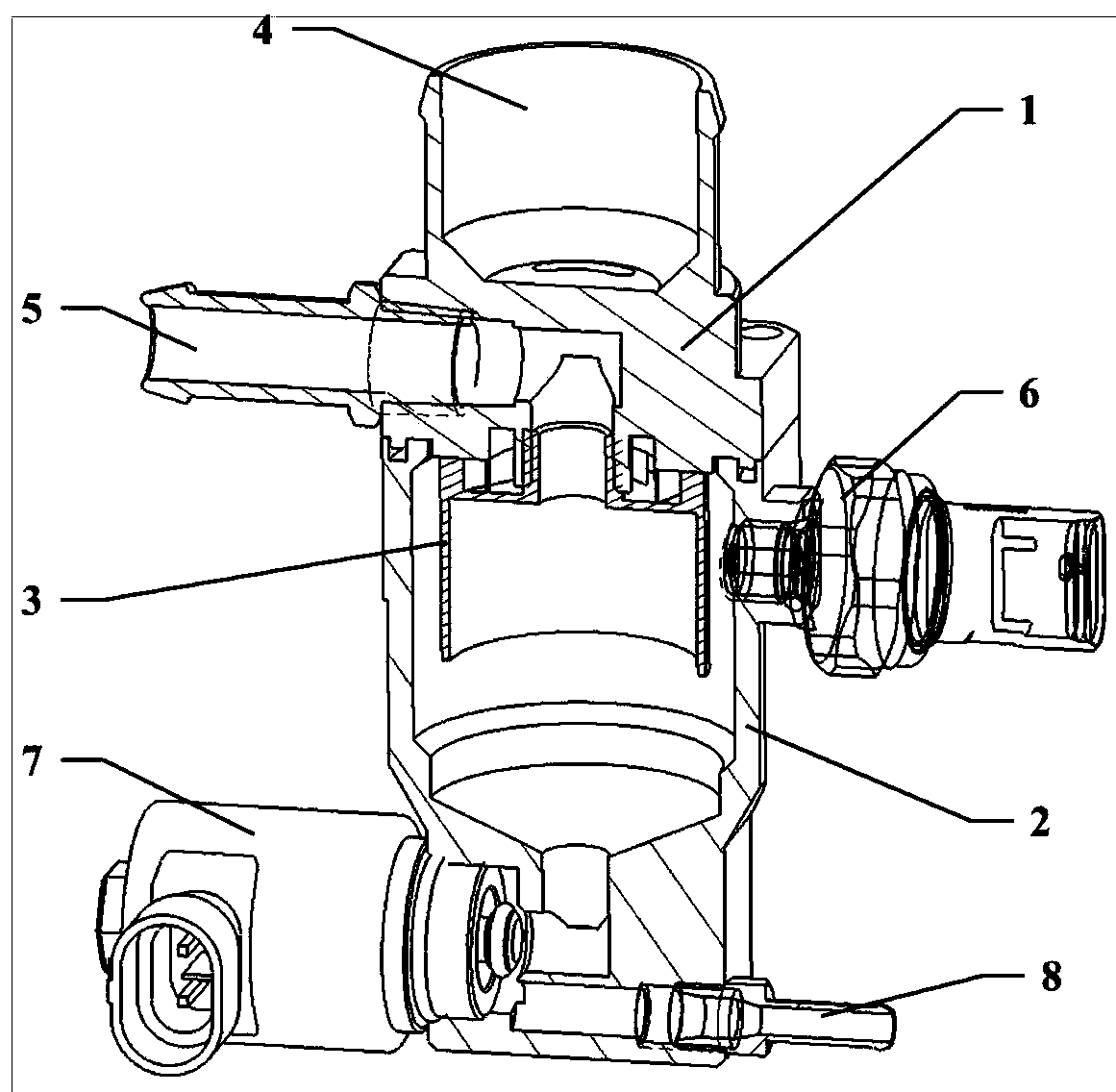
[0020] Please refer to figure 1 , the embodiment of the present invention provides a cyclone circulation filter gas-water separation device for a fuel cell system, including a housing, a sensor control system and a cyclone circulation filter component 3, the housing includes an upper cover 1 and an upper cover 1 Tank 2 integrally connected or detachably connected, the upper end of the upper cover 1 is provided with an inlet 4, the side wall of the upper cover 1 is provided with an outlet 5, the inside of the tank 2 is a hollow structure, the tank 2 is connected to the inlet 4 and the outlet 5 are connected, the lower end of the tank body 2 is provided with a drain port 8, and the sensor control system includes a sensor 6 and a drain solenoid valve 7. The sensor 6 is set on the tank body 2 or the upper cover 1, and the sensor 6 is a pressure sensor, a temperature sensor or a two-way valve. The sensor 6 is used to detect the pressure and temperature of the gas in the tank body 2, and the drain solenoid valve 7 is arranged at the drain outlet 8. After the drain solenoid valve 7 is opened, the water accumulated in the tank body 2 is drained by the drain outlet 8. discharge.
[0021] The cyclone circulating filter part 3 is installed directly under the upper cover 1 and is located in the tank body 2. The cyclone circulating filter part 3 can be installed under the upper cover 1 through bolts. Refer to figure 2 The cyclone circulation filter part 3 comprises some guide vanes 31, air outlets 32, some overflow ports 33 and beam tubes 34, the inside of the beam tubes 34 is a hollow structure, and the shape is cylindrical, and the air outlets 32 are integrally connected to the beam flow The upper end of pipe 34, the shape of gas outlet 32 ​​is cylindrical, and the diameter of gas outlet 32 ​​is less than the diameter of beam tube 34, and the inside of gas outlet 32 ​​and beam tube 34 is connected to form gas outlet channel, and the direction of gas outlet 32 ​​is with outlet 5 The direction of the guide vane 31 is integrally connected to the upper end of the beam tube 34, the guide vanes 31 are evenly arranged in a spiral shape along the outside of the air outlet 32, and one end of the guide vane 31 is connected to the upper end side of the beam tube 34 On the wall, the other end of the guide vane 31 gathers along the air outlet 32, the height of the guide vane 31 is slightly less than or equal to the height of the air outlet 32, and the profile of the guide vane 31 is a circular arc, an elliptical arc, etc., which are beneficial to the gas swirling flow The quasi-triangular or fan-shaped structure surrounded by the curved line, the gap between the guide vanes 31 forms a rotating flow channel, the direction of the rotating flow channel is perpendicular to the direction of the inlet 4 or at a certain angle, which can promote the airflow to form a strong rotation, Enhance the swirl strength of the air flow, prolong the liquid residence time, and effectively reduce the short-circuit flow through the outward swirl from the center, and improve the separation efficiency. The overflow port 33 is set at the upper end of the beam tube 34, The upper end sidewalls are arranged, and are located between the adjacent guide vanes 31, at the end of the guide vanes 31, the overflow port 33 makes the water in the inner wall of the beam tube 34 that may originally escape from the air outlet 32 ​​with the air flow pass through the overflow Port 33 recirculates into the tank body 2, thereby ensuring stable separation efficiency under different gas flow rates, and avoiding the problem of increased entrainment of water droplets in the outlet gas of traditional gas-water separators when the gas flow rate is large.
[0022] The working principle of the gas-water separation device provided by the present invention is: the hydrogen gas containing liquid water from the hydrogen gas outlet of the fuel cell stack enters from the inlet 4, and enters the gas outlet of the cyclone circulation filter part 3 through the gas distribution channel in the upper cover 1 32, and through the guide vane 31 to form a strong rotating air flow into the tank 2, the liquid water is separated to the side wall and bottom of the tank 2 under the action of centrifugal force and gravity, and the hydrogen bypasses the outer wall of the beam tube 34 Finally, it rotates into the inside of the beam tube 34, and passes through the air outlet 32, and is discharged from the outlet 5; the drain solenoid valve 7 at the bottom of the tank 2 is intermittently opened according to the set value, and the liquid water accumulated inside the tank 2 is drained from the drain 8 discharge.
[0023] When the flow rate of hydrogen gas to be processed is large, the increase of the flow velocity in the tank body 2 leads to the enhancement of the peristaltic ability of the liquid film, and the liquid water is easy to climb along the outer wall of the beam tube 34 to the beam tube 34 under the action of the high-speed air flow. The inner wall of the inner wall of the beam tube 34, the traditional structure will cause the reduction of the separation efficiency, but the cyclone circulation filter part 3 provided by the present invention will recirculate the liquid water that may be attached to the inner wall of the beam tube 34 to the side of the beam tube 34 through the overflow port 33 The outer wall, and the liquid water is brought to the inner wall of the tank body 2 by the high-speed air flow in the guide vane 31, and then separated to the bottom of the tank body 2, which ensures that the gas-liquid separation efficiency does not decrease when the hydrogen flow rate is large, and the beam flow The circulating swirling airflow on the wall surface of the tube 34 effectively prevents the formation of short-circuit flow.
[0024] The gas-water separation device provided by the present invention does not need to install a filter element, reduces the resistance of hydrogen circulation, and reduces the requirements for the working capacity of components such as hydrogen circulation pumps; there is no risk of freezing, and the ability of low-temperature cold start of fuel cells is improved. .
[0025] In this article, the orientation words such as front, rear, upper, and lower involved are defined by the parts in the drawings and the positions between the parts in the drawings, just for the clarity and convenience of expressing the technical solution. It should be understood that the use of the location words should not limit the scope of protection claimed in this application.
[0026] In the case of no conflict, the above-mentioned embodiments and features in the embodiments herein may be combined with each other.
[0027] The above descriptions are only preferred embodiments of the present invention, and are not intended to limit the present invention. Any modifications, equivalent replacements, improvements, etc. made within the spirit and principles of the present invention shall be included in the protection of the present invention. within range.

PUM

no PUM

Description & Claims & Application Information

We can also present the details of the Description, Claims and Application information to help users get a comprehensive understanding of the technical details of the patent, such as background art, summary of invention, brief description of drawings, description of embodiments, and other original content. On the other hand, users can also determine the specific scope of protection of the technology through the list of claims; as well as understand the changes in the life cycle of the technology with the presentation of the patent timeline. Login to view more.

Similar technology patents

Drying oven with double air channels for heat setting machine

InactiveCN104420037AEven and smooth airflowLow air resistanceTextiles and paperEnvironmental resistanceHeating system
Owner:WUXI CITY HUAYANG DYEING & FINISHING MACHINERY

Air intake service pipe assembly

InactiveCN111692026ASimple structureLow air resistanceMachines/enginesAir intakes for fuelStormwaterStructural engineering
Owner:DONGFENG COMML VEHICLE CO LTD

Classification and recommendation of technical efficacy words

  • Good gas permeability
  • Low air resistance

Directional energy-conducting smokeless moxibustion device based on separation membrane

InactiveCN110897873AGood gas permeabilityPrevent the generation of harmful gasesDevices for heating/cooling reflex pointsGas treatmentBiologyBiomedical engineering
Owner:广东泽蓝膜科技有限公司

A sensing device and cleaning apparatus

Owner:GUANGDONG WANJIALE KITCHEN TECH CO LTD

Preparation method of silicone rubber gas separation coating

InactiveCN112495194AHigh selectivityGood gas permeabilitySemi-permeable membranesDispersed particle separationPervaporationOrganosolv
Owner:北京迈安瑞科技有限公司

Light gas pipeline

InactiveCN101746378ALow air resistanceRun fastRailway tunnelsElectric propulsionGas pipelineProduct gas
Owner:彭智祥

Blade structure for centrifugal fans

InactiveCN102619783ALow air resistancePump componentsPumpsAgricultural engineeringAirflow
Owner:GUANGDONG CHIGO AIR CONDITIONING +2

Bicycle shift control device

InactiveUS20100037723A1Low air resistanceShaft for linear movementVariatorEngineering
Owner:TIEN HSIN INDS

Forced air cooling type heat dissipation case

PendingCN113747750ALow air resistanceImprove heat dissipation efficiency and heat dissipation effectModifications for power electronicsEngineeringForced air cooling
Owner:GUIYANG AVIATION MOTOR
Why Eureka
Try Eureka