Focusing method and device, terminal and computer storage medium

A focusing method and photodiode technology, which are applied in the parts and electrical components of TVs and color TVs, etc., can solve the problems of low focusing efficiency, loss of light input, and reduction of light transmission.

Active Publication Date: 2019-09-27
GUANGDONG OPPO MOBILE TELECOMM CORP LTD
View PDF14 Cites 2 Cited by
  • Summary
  • Abstract
  • Description
  • Claims
  • Application Information

AI Technical Summary

Problems solved by technology

[0003] At present, the commonly used PDAF mainly includes phase detection (Phase Detection, PD) focusing method and dual-core phase detection (DUAL PD) focusing method; for the phase detection focusing method, it is necessary to use a metal mask to monitor the pixels when focusing. Blocking, resulting in the loss of incoming light; fo...

Method used


Image

  • Focusing method and device, terminal and computer storage medium
  • Focusing method and device, terminal and computer storage medium
  • Focusing method and device, terminal and computer storage medium

Examples


Embodiment 1

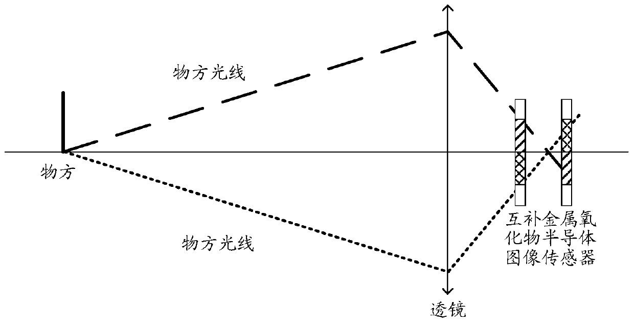
[0043] At present, PDAF is phase detection autofocus. The basic principle of PDAF is to perform phase detection by performing a certain shielding process on the photosensitive element, and to determine the offset value of the focus by calculating the distance and changes between pixels, so Compared with contrast focusing, phase focusing has a shorter focusing stroke, but due to the masking process, the light requirements will be higher.

[0044] figure 1 Schematic diagram of the imaging principle for PDAF technology focusing, such as figure 1 As shown, ray 1 represents the object-side ray passing through the upper half of the lens, and ray 2 represents the object-side ray passing through the lower half of the lens. It can be seen that when the CIS is in focus, the upper half of the CIS receives the It is the light in the upper part, and the CIS in the lower part receives the light in the lower part. On the contrary, it is just the opposite when it is out of focus. Then if yo...

Embodiment 2

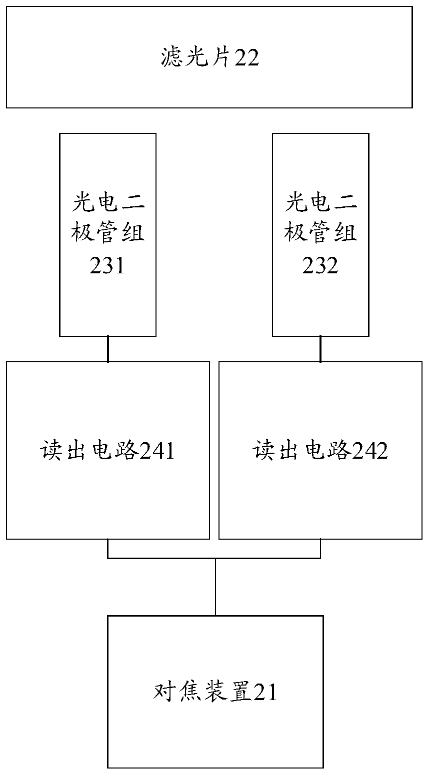
[0094] Figure 8 A schematic structural diagram of an optional focusing device provided in the embodiment of the present application, such as Figure 8 As shown, the focusing device is connected to the readout circuit of the CIS pixel structure, wherein the pixel structure also includes a filter and at least two groups of photodiodes, each group of photodiodes is connected to a corresponding readout circuit, and each group of photodiodes An isolation zone is provided between them; the device may include:

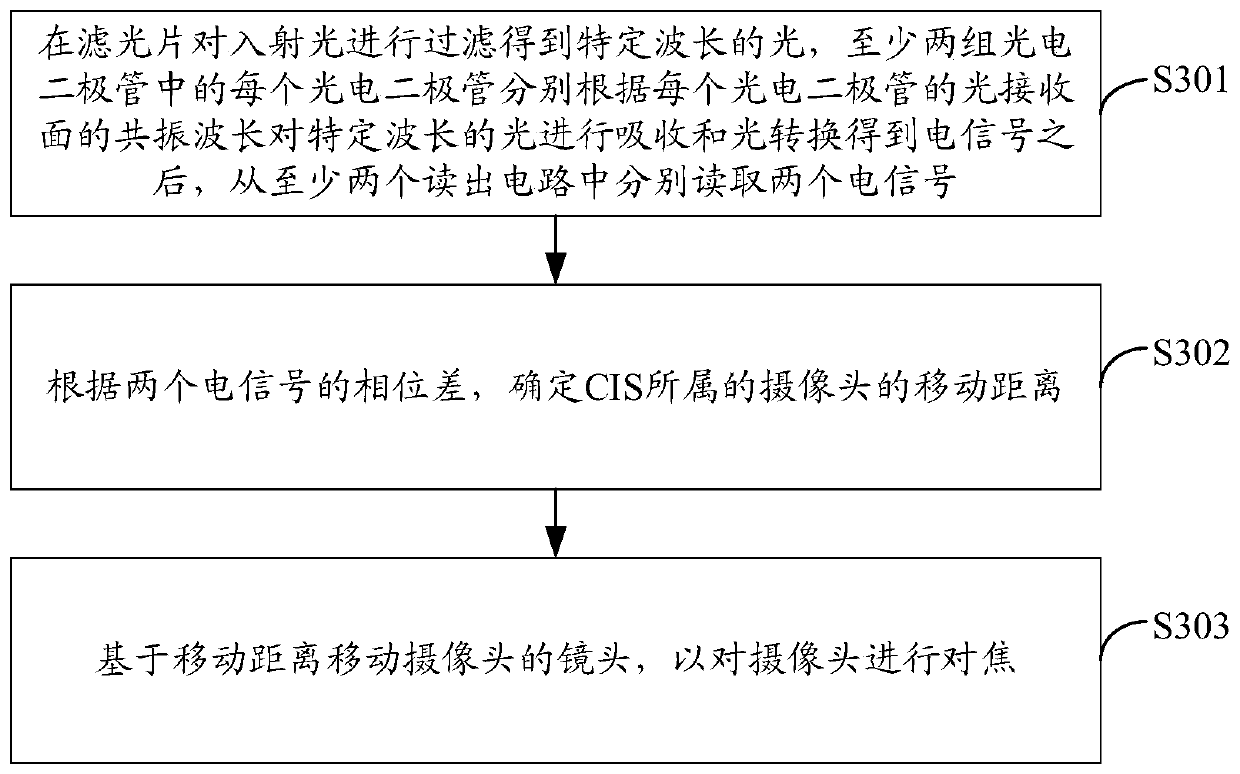
[0095] The reading module 81 is used to filter the incident light on the optical filter to obtain light of a specific wavelength, and each photodiode in at least two groups of photodiodes is respectively based on the resonance wavelength of the light receiving surface of each photodiode to the specific wavelength. After light is absorbed and light converted to obtain electrical signals, two electrical signals are respectively read from at least two readout circuits;

[009...


PUM

PropertyMeasurementUnit
Diameteraaaaaaaaaa
Diameteraaaaaaaaaa
Diameteraaaaaaaaaa

Abstract

The embodiment of the invention discloses a focusing method. The method is applied to a focusing device, the focusing device is connected with a reading circuit of a pixel structure of a CIS, the pixel structure further comprises an optical filter and at least two sets of photodiodes, each set of photodiodes is correspondingly connected with one reading circuit, and an isolation region is arranged between each set of photodiodes; the method comprises the following steps of: oincident light is filtered by the optical filter to obtain light with a specific wavelength; each photodiode absorbs light with a specific wavelength and converts the light into an electric signal according to the resonant wavelength of the light receiving surface of each photodiode; two electric signals are read from the at least two reading circuits respectively, the moving distance of the camera to which the CIS belongs is determined according to the phase difference of the two electric signals, and the lens of the camera is moved based on the moving distance so as to focus the camera. The embodiment of the invention further provides a focusing device, a terminal and a computer storage medium.

Description

technical field [0001] The present application relates to a focusing technology of a Complementary Metal Oxide Semiconductor Image Sensor (CIS, Complementary Metal Oxide Semiconductor Image Sensor) image sensor in a terminal, and in particular to a focusing method, device, terminal and computer storage medium. Background technique [0002] There are two main autofocus methods of cameras: contrast focus and phase focus. Among them, phase detection autofocus (PDAF) is phase detection autofocus. Phase detection autofocus technology has been very mature in the field of digital cameras. [0003] At present, the commonly used PDAF mainly includes phase detection (Phase Detection, PD) focusing method and dual-core phase detection (DUAL PD) focusing method; for the phase detection focusing method, it is necessary to use a metal mask to monitor the pixels when focusing. Blocking, resulting in the loss of incoming light; for the dual-core phase detection focusing method, when focusing...

Claims


Application Information

Patent Timeline
IPC IPC(8): H04N5/232H04N5/374H04N5/378
CPCH04N23/67H04N25/76H04N25/75
Inventor 杨鑫
Owner GUANGDONG OPPO MOBILE TELECOMM CORP LTD
Why Eureka
Try Eureka