A new type of automatic stroke unloading valve assembly

A technology of automatic stroke and unloading valve, which is applied in the direction of fluid pressure actuator, servo motor assembly, fluid steering mechanism, etc. It can solve the problems of inability to accurately guarantee the coaxiality of both ends, troublesome maintenance of unloading mechanism, and high maintenance cost. problems, to achieve the effect of promoting reliability, reducing maintenance costs, and reducing maintenance frequency

Active Publication Date: 2021-04-23
SICHUAN YAAN HANGQING ELECTRICAL APPLIANCE
View PDF5 Cites 0 Cited by
  • Summary
  • Abstract
  • Description
  • Claims
  • Application Information

AI Technical Summary

Problems solved by technology

[0009] The purpose of the present invention is to provide a new type of automatic stroke unloading valve assembly, which solves the problem that the existing unloading mechanism is a separate structure, and the steps of directly assembling it on the rack piston are cumbersome and cannot accurately ensure the balance between the two ends. Coaxiality, poor reliability, troublesome post-maintenance of this unloading mechanism, high maintenance cost and many other technical problems mentioned above

Method used


Image

  • A new type of automatic stroke unloading valve assembly
  • A new type of automatic stroke unloading valve assembly
  • A new type of automatic stroke unloading valve assembly

Examples


Embodiment 1

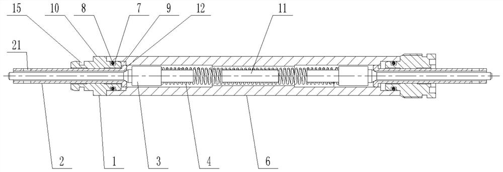
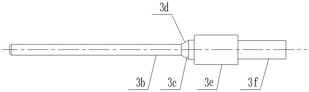
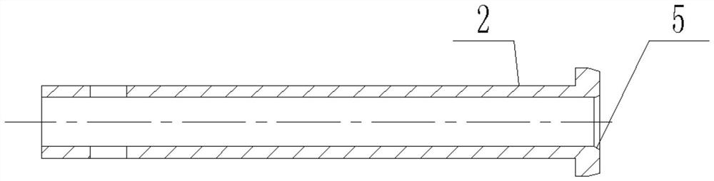
[0035] Such as Figure 1-Figure 3 As shown, a new type of automatic stroke unloading valve assembly of the present invention includes a valve tube 6 coaxial with each other, a pressure spring 4 and an unloading valve mechanism, and the unloading valve mechanism includes a sleeve seat 1 coaxial with each other, The limit sleeve 2 and the valve stem 3, wherein the sleeve seat 1 is fixed on one end of the valve tube 6, and the sleeve seat 1 is sleeved on the limit sleeve 2 and has an interference fit with the limit sleeve 2 ; One end of the limit sleeve 2 away from the center point of the valve tube 6 passes through the center hole of the sleeve seat 1, and a tapered hole is provided on the center hole of the limit sleeve 2 near the center point of the valve tube 6 5; the valve stem 3 includes a coaxial long rod 3b and a matching shaft 3c which are sequentially connected and coaxial. The matching shaft 3c is in the shape of a truncated cone, and its small-diameter end is connecte...

Embodiment 2

[0042] This embodiment is based on Embodiment 1, and further implements the description of the structure of the valve stem 3 .

[0043] Such as figure 2 As shown, in the present invention, a limiting shaft 3e is provided at the large diameter end of the matching shaft 3c, the axis of the limiting shaft 3e is collinear with the axis of the matching shaft 3c, and one end thereof is connected to the matching shaft 3c, and The limit shaft 3e is in interference fit with the center hole of the limit sleeve 2;

[0044] Both ends of the pressure spring 4 are respectively in contact with the end faces of a limiting shaft 3e.

[0045] Since the connection between the inside of the installation hole and the oil chamber where the rack piston is located is controlled by whether the conical surface on the unloading valve stem contacts the conical surface on the limit spring sleeve, and the long rod on the unloading valve stem There is a clearance fit between the position and the limit sp...

Embodiment 3

[0050] This embodiment is based on the embodiment 1, and is further described for the cooperation structure between the valve tube 6 and the sleeve seat 1 .

[0051] Such as Figure 1-Figure 3 As shown, in the present invention, an annular groove A7 is provided on the side wall of the sleeve seat 1 close to the valve tube 6, and the axis of the annular groove A7 coincides with the axis of the sleeve seat 1. The sealing ring A8 is set in A7, and the end close to the valve tube 6 on the side wall of the limit sleeve 2 is inserted into the central hole of the valve tube 6, and the inner and outer rings of the sealing ring A8 are connected with the groove of the annular groove A7 respectively. The bottom and the central hole of the valve pipe 6 are interference fit.

[0052] The annular groove A7 is preferably a rectangular groove, and the sealing ring A8 is preferably an O-shaped rubber sealing ring.

[0053] Further, both ends of the center hole of the valve tube 6 are provide...


PUM


Abstract

The invention discloses a novel automatic stroke unloading valve assembly, which includes a valve tube, a pressure spring and an unloading valve mechanism. The unloading valve mechanism includes a bushing seat, a limiting bushing and a valve stem. One end of the tube; one end of the central hole of the limit sleeve is provided with a tapered hole; the valve stem includes a long rod b and a matching shaft c, the matching shaft c is in the shape of a truncated cone, and its small diameter end is connected with one end of the long rod b. The conical side wall d is in contact with the tapered hole wall, and the other end of the long rod b passes through the center hole of the limit sleeve; there are two unloading valve mechanisms, which are respectively located at both ends of the valve tube, and the pressure spring is located at the two unloading valves. between the load mechanism and in a compressed state. The present invention separates the original detached structure for unloading from the rack piston to form an integral structure and an independent valve body, which improves the accuracy and reliability of the overall structure of the unloading component.

Description

technical field [0001] The invention relates to the field of automobiles, in particular to a novel automatic stroke unloading valve assembly. Background technique [0002] The steering gear is a mechanical device that will be manned or unmanned and has a power source, so that it can randomly change the running route and direction during operation. The steering gear is commonly known as the steering gear and the steering gear, and it is the most important part of the steering system. Its function is to increase the force transmitted from the steering wheel to the steering transmission mechanism and to change the direction of force transmission. [0003] When the car turns to the limit position, the oil pressure of the power steering gear reaches the maximum oil pressure, the steering oil pump is at the maximum load state, and the hydraulic system maintains high pressure for a long time. If the oil pressure is not lowered, the temperature of the steering oil will rise, which ...

Claims


Application Information

Patent Timeline
Patent Type & Authority Patents(China)
IPC IPC(8): B62D5/08F15B13/02
CPCB62D5/08F15B13/024
Inventor 吴国庆
Owner SICHUAN YAAN HANGQING ELECTRICAL APPLIANCE
Why Eureka
Try Eureka