High-sensitivity optical fiber grating acceleration sensor based on rigid hinge

A technology of acceleration sensor and optical fiber grating, which is applied in the direction of acceleration measurement using inertial force, and can solve problems such as real-time measurement and processing errors, affecting the normal operation of the machine, and large processing errors.

Active Publication Date: 2019-10-01
WUHAN UNIV OF TECH
View PDF9 Cites 2 Cited by
  • Summary
  • Abstract
  • Description
  • Claims
  • Application Information

AI Technical Summary

Problems solved by technology

In the actual processing process, micro-vibration is almost difficult to avoid. If the vibration direction is consistent with the error-sensitive direction, it will cause large processing errors, increase the roughness of the part surface, and even affect the normal operation of the machine. Therefore, it is necessary to set the acceleration Sensors detect micro-vibrations during actual machining
[0003] Although fiber gratings have outstanding advantages such as small size, light weight, no electromagnetic interference, and distributed measurement, the current fiber grating acceleration sensors basically use cantilever beams or flexible hinges as elastic bodies and mass blocks as The method of acceleration carrier, due to the principle of continuity of the elastic body, the surrounding material must have constraints on the deformed material, which actually reduces the total axial deformation of the fiber grating. The sensor designed in this way has low sensitivity and cannot It can measure the machining error caused by micro-vibration very well in real time

Method used


Image

  • High-sensitivity optical fiber grating acceleration sensor based on rigid hinge
  • High-sensitivity optical fiber grating acceleration sensor based on rigid hinge
  • High-sensitivity optical fiber grating acceleration sensor based on rigid hinge

Examples


Embodiment 1

[0041] Taking Embodiment 1 as an example, the assembly and working steps are as follows:

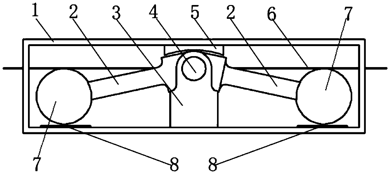
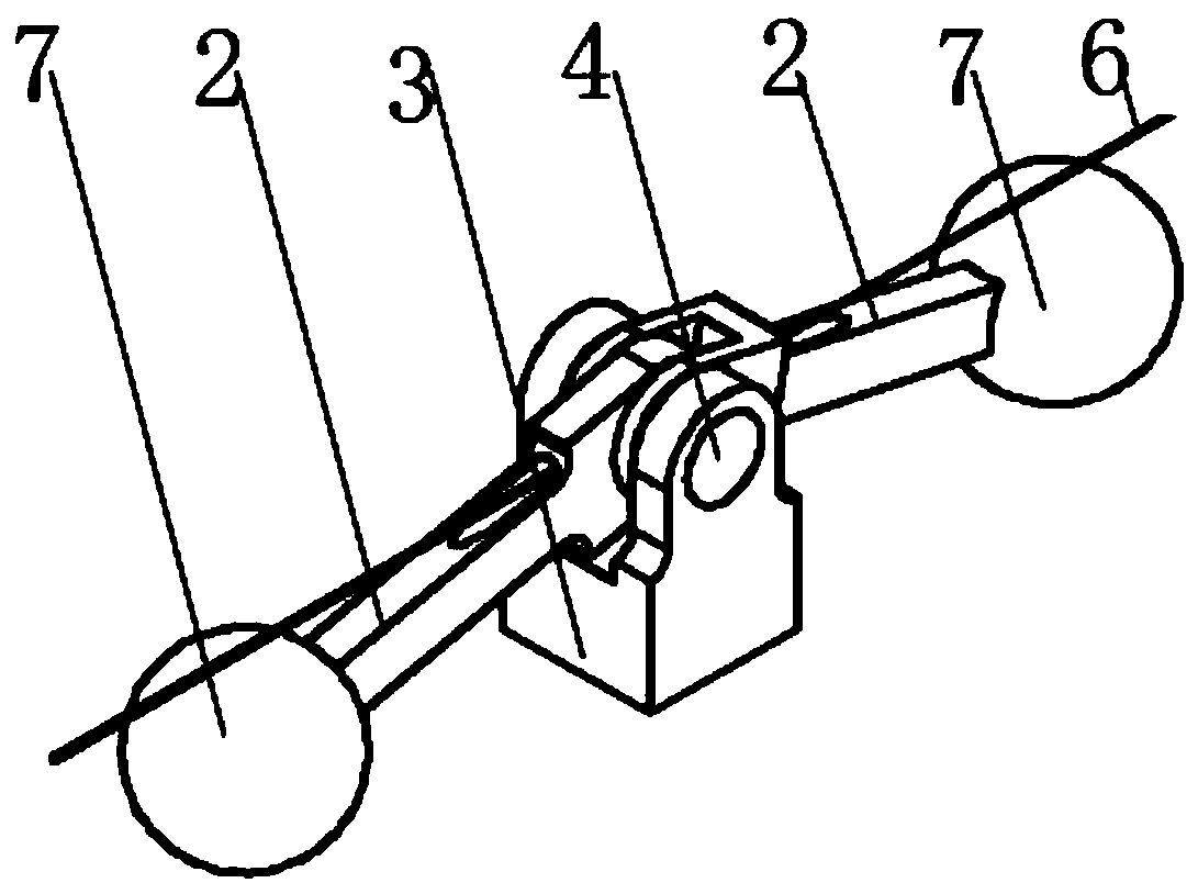
[0042] S1. Put the base 1 on a horizontal surface, then put a swing rod 2 into the notch of the base 3 and align the hinge hole 10 of the swing rod 2 with the hinge hole 10 of the base 3 .

[0043] S2. Put another pendulum 2 into the notch of the first pendulum 2 and align the hinge holes 10 of the two.

[0044] S3, make the center line of the optical fiber of the pin shaft 4 pass through the hole 9 in the horizontal plane, draw a horizontal line on the end faces of the base 3 and the pin shaft 4 with a colored pen at the same time and extend it to the edge of the base 3, so that the optical fiber of the pin shaft 4 The central line of the passing hole 9 coincides with the central line of the optical fiber passing through the hole 9 of the two swing rods 2 .

[0045] S4. Align the horizontal line on the end face of the pin shaft 4 with the horizontal line on the base 3, slowly insert th...


PUM


Abstract

The invention discloses a high-sensitivity optical fiber grating acceleration sensor based on a rigid hinge. The high-sensitivity optical fiber grating acceleration sensor comprises an optical fiber,a package shell, a base fixed on an inner bottom surface of the package shell, and a pin shaft, two oscillating bars and mass blocks which are fixed on a base; one end of each oscillating bar can hinge with the base in a way of shaking up and down through the pin shaft, thereby forming rigid hinge, and the other end is fixed on the mass block; two oscillating bars and the mass block are symmetricabout the pin shaft center line; when adopting a single optical fiber, the optical fiber is horizontally fixed on the highest point or lowest point of two mass blocks; when adopting two optical fibers, two optical fibers are horizontally fixed at the highest point and the lowest point of two mass blocks; the part between two fixation points on the optical fiber is the optical fiber work section, gratings are arranged at two sides of the pin shaft center line on the optical fiber work section, the optical fiber work section has a certain prestress and cannot contact with other parts; the mass blocks are free from contacting with the package shell, and two ends of the optical fiber are connected to an interrogator after penetrating through the package shell. The sensor disclosed by the invention can realize the precise measurement of the micro-vibration.

Description

technical field [0001] The invention belongs to the technical field of fiber grating sensing, and in particular relates to a high-sensitivity fiber grating acceleration sensor based on a rigid hinge. Background technique [0002] In recent years, the manufacturing of mechanical parts tends to develop more and more in the direction of precision, miniaturization and light weight, and precision machining technology occupies an important position in the process of precision parts manufacturing. Precision machining technology refers to the size and shape accuracy of processing. Sub-micron level, the roughness R of the machined surface a A general term for technologies that reach the nanoscale. In the actual processing process, micro-vibration is almost difficult to avoid. If the vibration direction is consistent with the error-sensitive direction, it will cause large processing errors, increase the roughness of the part surface, and even affect the normal operation of the machin...

Claims


Application Information

Patent Timeline
Patent Type & Authority Applications(China)
IPC IPC(8): G01P15/03
CPCG01P15/03
Inventor 谭跃刚谢志超刘虎黄兵毛健
Owner WUHAN UNIV OF TECH
Why Eureka
Try Eureka