
Clean workshop

A technology for cleaning workshops and workshops, which is applied in the field of flat panel display manufacturing, and can solve the problems of increased number of fan filter units 8, low heat generation of equipment, and increased space

Inactive Publication Date: 2019-10-08
S Y TECH ENG & CONSTR CO LTD
View PDF9 Cites 7 Cited by
  • Summary
  • Abstract
  • Description
  • Claims
  • Application Information

AI Technical Summary

Problems solved by technology

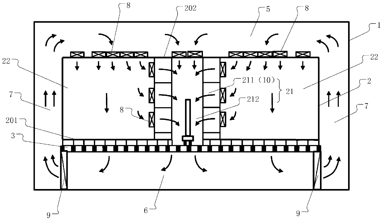
The air circulation path of the whole clean room purification air conditioning system is as follows: figure 1 As shown by the arrow in the figure, wherein, since the air in the process production area 22 is inhaled by the fan filter unit 8 installed on the side of the material storage rack 10, an additional arrangement on the ceiling 202 of the process production area 22 and the side of the material storage rack 10 are required. The fan filter unit installed with the same air volume will greatly increase the number of fan filter units 8 that need to be installed on the ceiling 202 of the process production area 22. Similarly, the energy consumption will also increase accordingly.
[0005] In addition, the cleanliness requirements of the material storage area 211 and the material transfer area 212 are very strict, and it is necessary to ensure a large amount of air supply of the cleanliness level, but the heat generated by the equipment in this area is very small, so the air flowing through this area Only a very small portion of the stream needs to be cooled, but according to figure 1 In the traditional clean room 2 construction method shown, the airflow inhaled by the fan filter unit 8 installed on the top of the material transfer area 212 and the fan filter unit 8 installed on the side wall of the material storage rack 10 all passes through the dry cooling coil 9, the treated airflow, and at the same time, after entering the lower technical interlayer 6, the airflow flowing out from the process production area 22 and the material transfer area 212 has all passed through the dry cooling coil 9, resulting in a large increase in the number of dry cooling coils 9, resulting in In many projects, the dry cooling coil 9 cannot be arranged in the specified space; moreover, the airflow sent from the process production area 22 and the material transfer area 212 all passes through the technical interlayer 7 and the upper technical interlayer 5, resulting in the technical interlayer 7 and the upper technical interlayer 5. The space required for the upper technical mezzanine 5 increases, increasing construction costs

Method used


Image

  • Clean workshop
  • Clean workshop
  • Clean workshop

Examples


Embodiment Construction

[0035] In order to make the object, technical solution and advantages of the present invention clearer, the present invention will be described in further detail below in conjunction with the accompanying drawings. Apparently, the described embodiments are only some of the embodiments of the present invention, rather than all of them. Based on the embodiments of the present invention, all other embodiments obtained by persons of ordinary skill in the art without making creative efforts belong to the protection scope of the present invention.

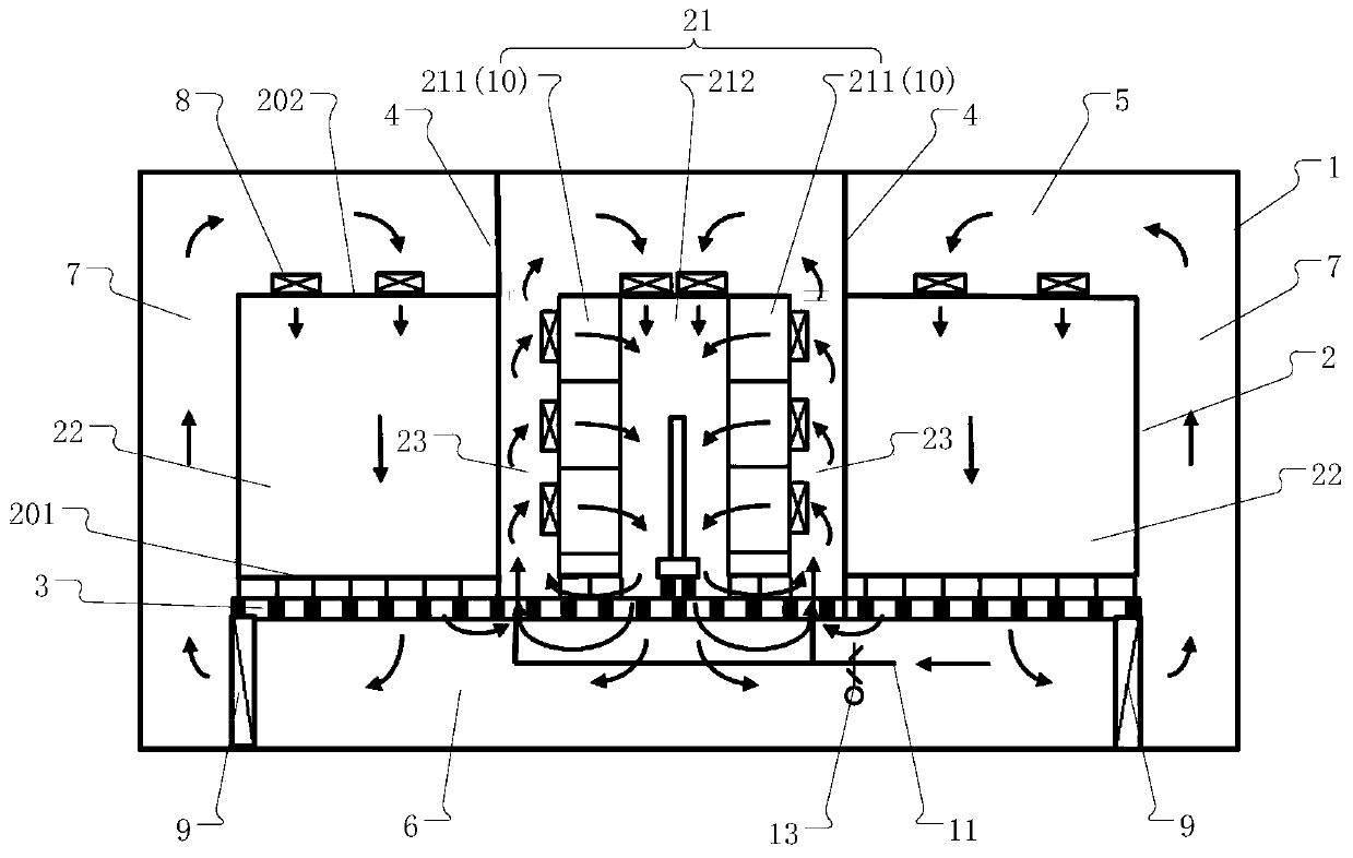
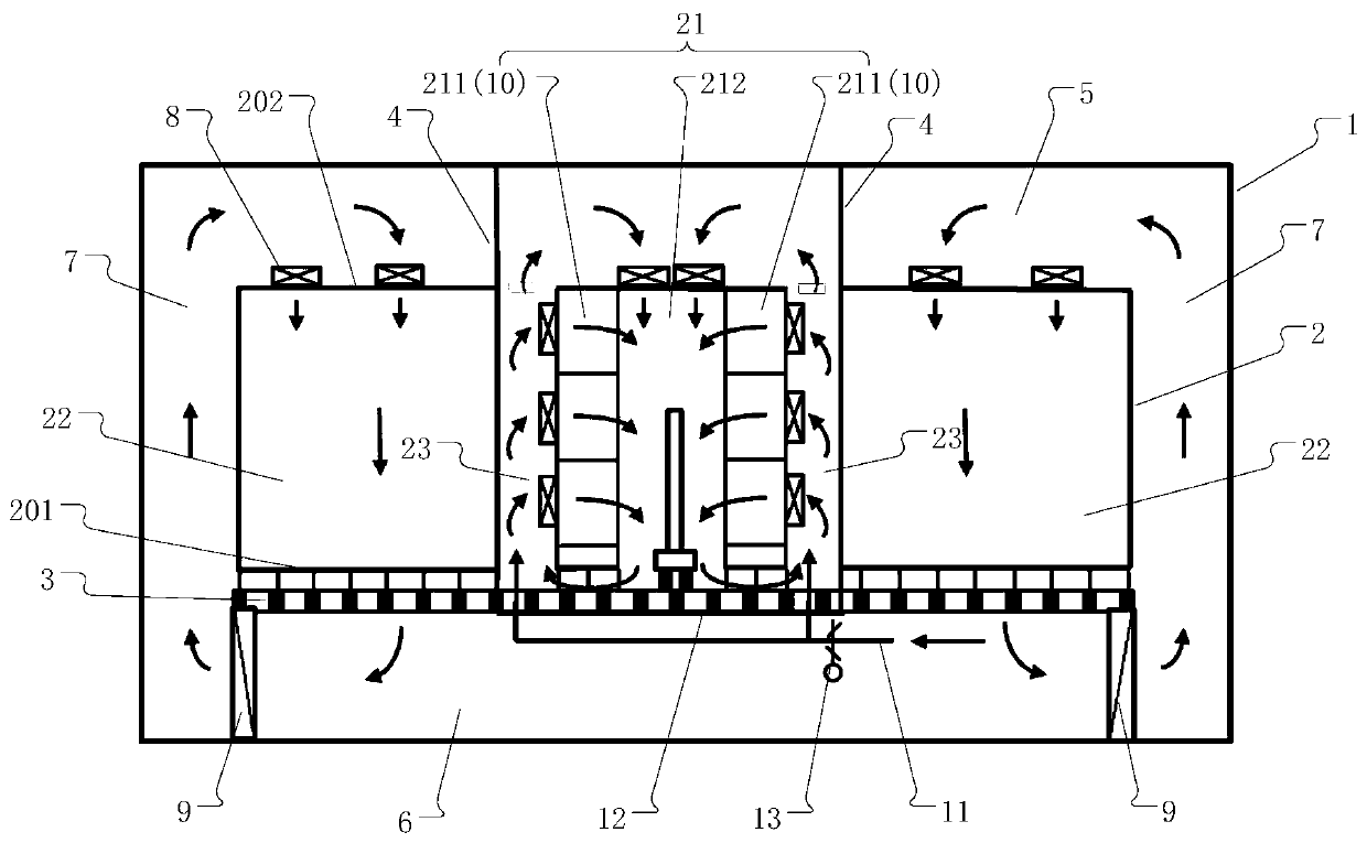
[0036] The embodiment of the present invention provides a clean factory building, by setting a partition wall panel extending to the top of the upper technical interlayer in the clean room, and forming a return air passage between the partition wall panel and the material storage rack that communicates with the upper technical interlayer and the material transmission area , so as to optimize the air circulation path of the clean room puri...


PUM


Abstract

The invention relates to the technical field of flat panel display production and manufacturing, and discloses a clean workshop. A material storage and transfer area and process production areas whichare positioned on the two sides of the material storage and transfer area are arranged in a clean room; a material storage rack group is arranged in the material storage and transfer area; partitionpanels are arranged on the two sides of the material storage rack group; the top of each partition board extends to the top of an upper technical interlayer, and the bottom of each partition board isconnected with a wafer board; the material storage rack group comprises two rows of material storage racks; an air return passage is formed by the gap between each row of the material storage racks and the adjacent partition board and communicates with the upper technical interlayer; a plurality of fan filter units are arranged on each row of the material storage racks; a material transfer area isformed between two rows of the material storage racks; an air flow channel which communicates with the material transfer area and the adjacent air return passage is formed in the bottom of each row of the material storage rack; a fresh air supply pipe is arranged in a lower technical interlayer; and an air outlet of the fresh air supply pipe communicates with each air return passage.

Description

technical field [0001] The invention relates to the technical field of flat panel display production and manufacturing, in particular to a clean workshop. Background technique [0002] At present, the mainstream products of the electronics industry are semiconductor chips and flat panel display devices. Due to the precision processing requirements in the production process, the production environment requires strict cleanliness levels. Therefore, the processing and production of semiconductor chips and flat panel display devices need to be in clean rooms. The cleanliness level in the clean room is maintained by sending clean air into the room through the fan filter unit installed on the ceiling, and discharging the suspended particles in the room from the return air outlet. Traditional clean workshops such as figure 1 As shown, including the plant body 1, the plant body 1 is provided with an upper technical mezzanine 5, a lower technical mezzanine 6, and a clean production ...

Claims


Application Information

Patent Timeline
IPC IPC(8): F24F3/16F24F13/28F24F11/74
CPCF24F13/28F24F11/74F24F3/167
Inventor 秦学礼张群肖红梅阎冬李鹏
Owner S Y TECH ENG & CONSTR CO LTD
Learn More