Multilevel centralized parameter power distribution circuit for frequency modulation frequency band

A technology of power distribution circuit and centralized parameters, which is applied in the direction of printed circuits and electrical components connected by circuits, non-printed electrical components, etc., which can solve the problems of reducing circuit board volume, long wavelength of FM frequency band, and high insertion loss.

Pending Publication Date: 2019-10-08
杭州长泽科技有限公司
View PDF0 Cites 2 Cited by
  • Summary
  • Abstract
  • Description
  • Claims
  • Application Information

AI Technical Summary

Problems solved by technology

[0005] Therefore, the balance of the distributor, insertion loss, port standing wave, and isolation between ports are some of its particularly important indicators. Considering the convenience of use, it is generally required that the volume of the distributor be as small as possible to withstand power. As large as possible; however, its wavelength is longer in the FM frequency band, and the traditional splitter manufacturing method is difficult to meet the small siz

Method used


Image

  • Multilevel centralized parameter power distribution circuit for frequency modulation frequency band
  • Multilevel centralized parameter power distribution circuit for frequency modulation frequency band
  • Multilevel centralized parameter power distribution circuit for frequency modulation frequency band

Examples


Example Embodiment

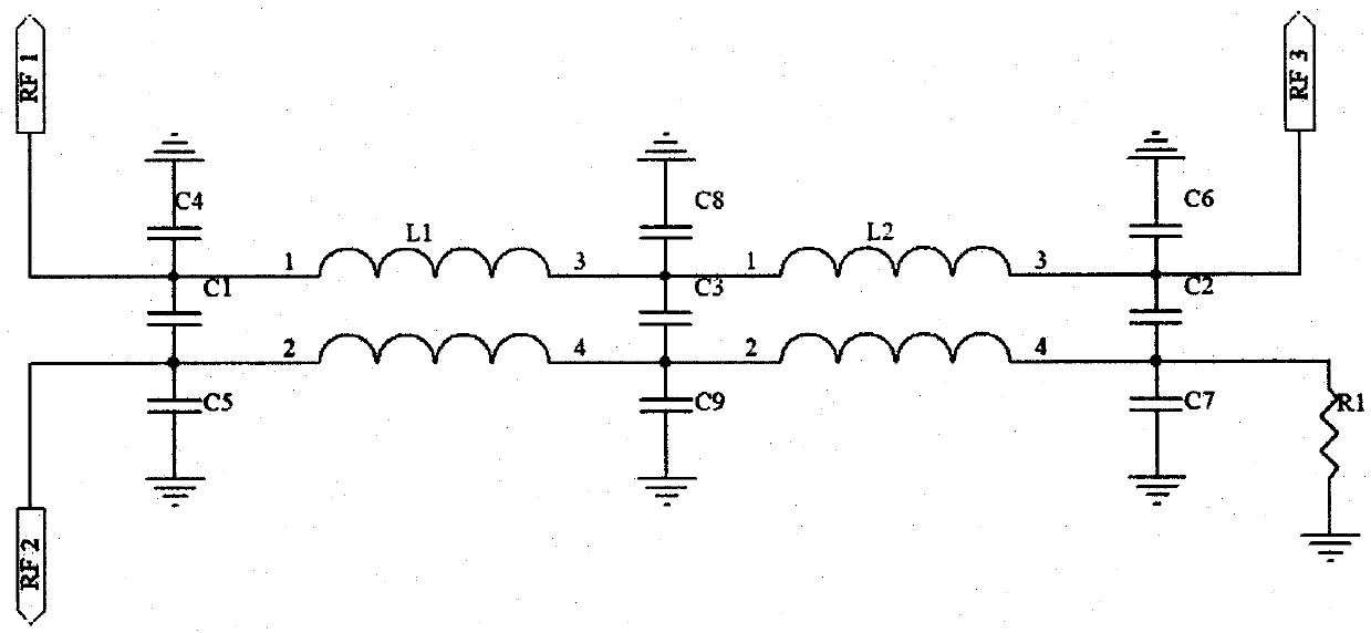
[0019] The circuit principle of the present invention is as follows. The radio frequency signal is input to the quadrature bridge from port 1 and output from port 3 and port 4. The output level and amplitude are approximately equal, and the phase difference of the output signal is 90°. The two radio frequency signals are respectively from port 3 and port 4 inputs, synthesized output from port 1.

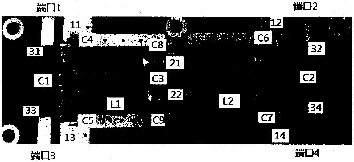
[0020] image 3 It is a schematic diagram of the structure of an embodiment of this patent.

[0021] This patent proposes an embodiment of a twisted wire radio frequency quadrature bridge, and its structure is as follows image 3 As shown, the rectangular copper-clad printed board is corroded into multiple symmetrical copper-clad patches. As shown in the figure, there are four grounding patches 11-14 around the printed board, and two in the middle of the printed board. Microstrip lead patch 21-22, the two ends of the twisted wire mutual inductance coils L1 and L2 are respectively welded t...


PUM


Abstract

The invention mainly discloses a multilevel centralized parameter power distribution circuit for a frequency modulation frequency band, which can greatly reduce the excessive large distribution circuit area of the frequency modulation frequency band due to the wavelength problem, improve distribution balance, reduce circuit insertion loss and is particularly applicable to high power distributionand multi-antenna distribution circuits in the frequency modulation frequency band. The method is mainly characterized in that the whole circuit is composed of mutual inductance coils, coupling capacitors between self-inductance coils and terminals distributed symmetrically and grounding capacitors; and the whole circuit is small in size and compact in structure without any additional loss causedby other magnetic and other loss devices. The method is further specifically characterized in that the circuit is extended to be composed of a two-level twisted mutual inductance coil, a two-level self-inductance coil, a distributed end-to-end coupling capacitor and a to-ground coupling capacitor on the basis of a single-level twisted mutual inductance coil and a single-level self-inductance coil. The mode can greatly improve the radio frequency bandwidth and greatly reduce the insertion loss.

Description

Technical field [0001] The invention relates to a frequency-modulation frequency band multi-level centralized parameter power distribution circuit rate distribution field, which belongs to the technical improvement of the traditional orthogonal power distribution circuit; in particular, it relates to a multi-level centralized parameter power distribution circuit; the traditional distribution circuit generally adopts a transmission line transformer form or distribution Orthogonal form of parametric form. The orthogonal circuit in the form of a transmission line transformer is mainly composed of a ferrite magnetic ring, which is the primary culprit of insertion loss, which will cause excessive insertion loss, and large insertion loss will cause serious heat generation, so it cannot Achieve high-power distribution; and because the FM frequency band is lower and the wavelength is longer, the size of the distribution circuit in the form of distributed parameters will be particularly ...

Claims


Application Information

Patent Timeline
IPC IPC(8): H01P5/12H01P3/08H05K1/18
CPCH01P3/08H01P5/12H05K1/18
Inventor 许艳苇冯云萍柴江南方峥
Owner 杭州长泽科技有限公司
Why Eureka
Try Eureka