
Lead cutting, stripping and twisting device and lead cutting, stripping and twisting method

A technology for twisting wires and wires, which is applied in the field of wire cutting, stripping, and rubbing devices. It can solve the problems of inaccurate alignment of the first cutter assembly and the second cutter assembly, easy displacement of wire ends, and poor tinning effect, etc. problem, to achieve the effect of avoiding mutual interference, avoiding scattered splitting, and good tinning effect

Pending Publication Date: 2019-10-08
TAIZHOU HAORAN MACHINERY MFG
View PDF1 Cites 4 Cited by
  • Summary
  • Abstract
  • Description
  • Claims
  • Application Information

AI Technical Summary

Problems solved by technology

[0002] In the electronic component welding machine, it is necessary to connect various electronic components to the wires by welding, and the wires need to be cut and stripped before tinning, but when multi-core wires are used, the wires after stripping directly, The core wire is extremely loose, the effect of tin dipping is not good, and it is easy to desolder. Chinese patent [authorized announcement number: CN 207664431 U] discloses a knife holder mechanism that can cut and strip wires and twist wires, including: knife holder seat, scissors The cutting assembly and the twisting mechanism, the cutting assembly includes first and second cutting knife assemblies slidingly arranged on the knife holder seat, and a shearing drive mechanism capable of driving the first and second cutting knife assemblies to move relatively; the twisting The thread mechanism is arranged on the knife rest seat, which includes the first and second thread rubbing arm assemblies slidably arranged on the knife rest seat, and the closing drive mechanism that can drive the first and second thread rubbing arm assemblies to move relatively close to or away from , A twisting drive mechanism capable of driving the first and second twisting arm assemblies to move relative to each other
When it is working, it can first use the cutting assembly to cut the wire, and then control the interval between the first cutter assembly and the second cutter assembly to strip the wire. The rubbing arm assembly rubs the core wires after stripping, so that the core wires are twisted together to prevent them from loosening and to ensure the effect of tinning. However, the cutting and stripping of the wires in this patent use the first cutter component and the second cutter assembly, and the wire cutting and stripping operations are two distributed operations before and after the process, which consumes a relatively long time. In addition, because the cutting operation requires the first cutter assembly and the second cutter assembly to be completely closed, The stripping operation needs to be completed using the interval between the first cutter assembly and the second cutter assembly, which is inconvenient for debugging, and in actual production, when multiple wires need to be cut, stripped and twisted at the same time, because the ends of the wires are in the It is easy to shift after cutting, and it is easy to cause the first cutter assembly and the second cutter assembly to be inaccurate during stripping

Method used


Image

  • Lead cutting, stripping and twisting device and lead cutting, stripping and twisting method
  • Lead cutting, stripping and twisting device and lead cutting, stripping and twisting method
  • Lead cutting, stripping and twisting device and lead cutting, stripping and twisting method

Examples


Embodiment Construction

[0030] The following are specific embodiments of the present invention and in conjunction with the accompanying drawings, the technical solutions of the present invention are further described, but the present invention is not limited to these embodiments.

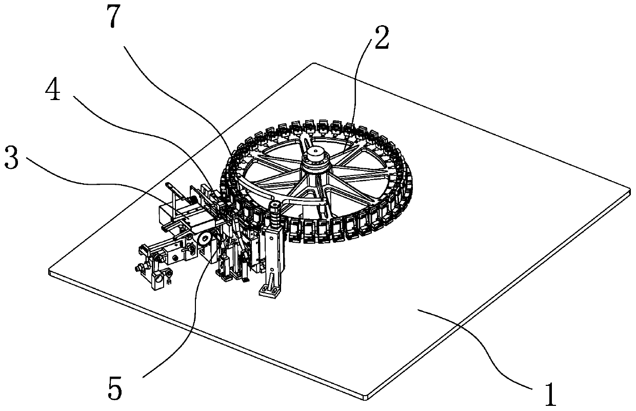
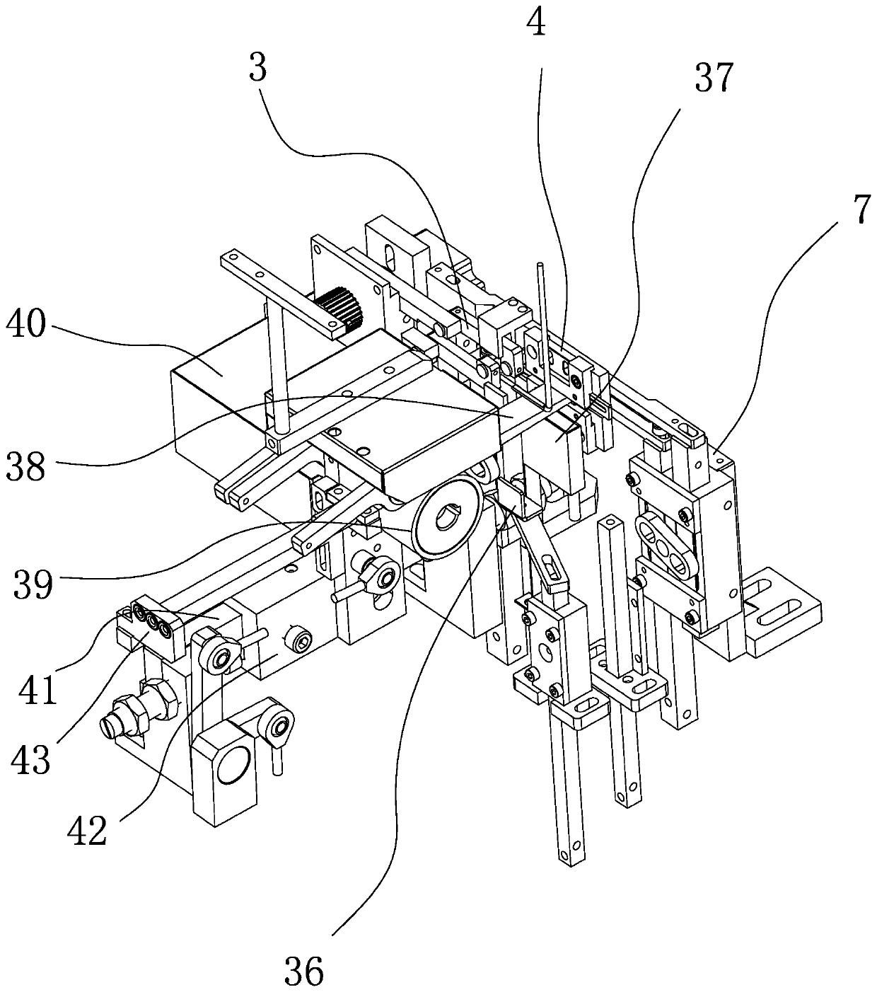
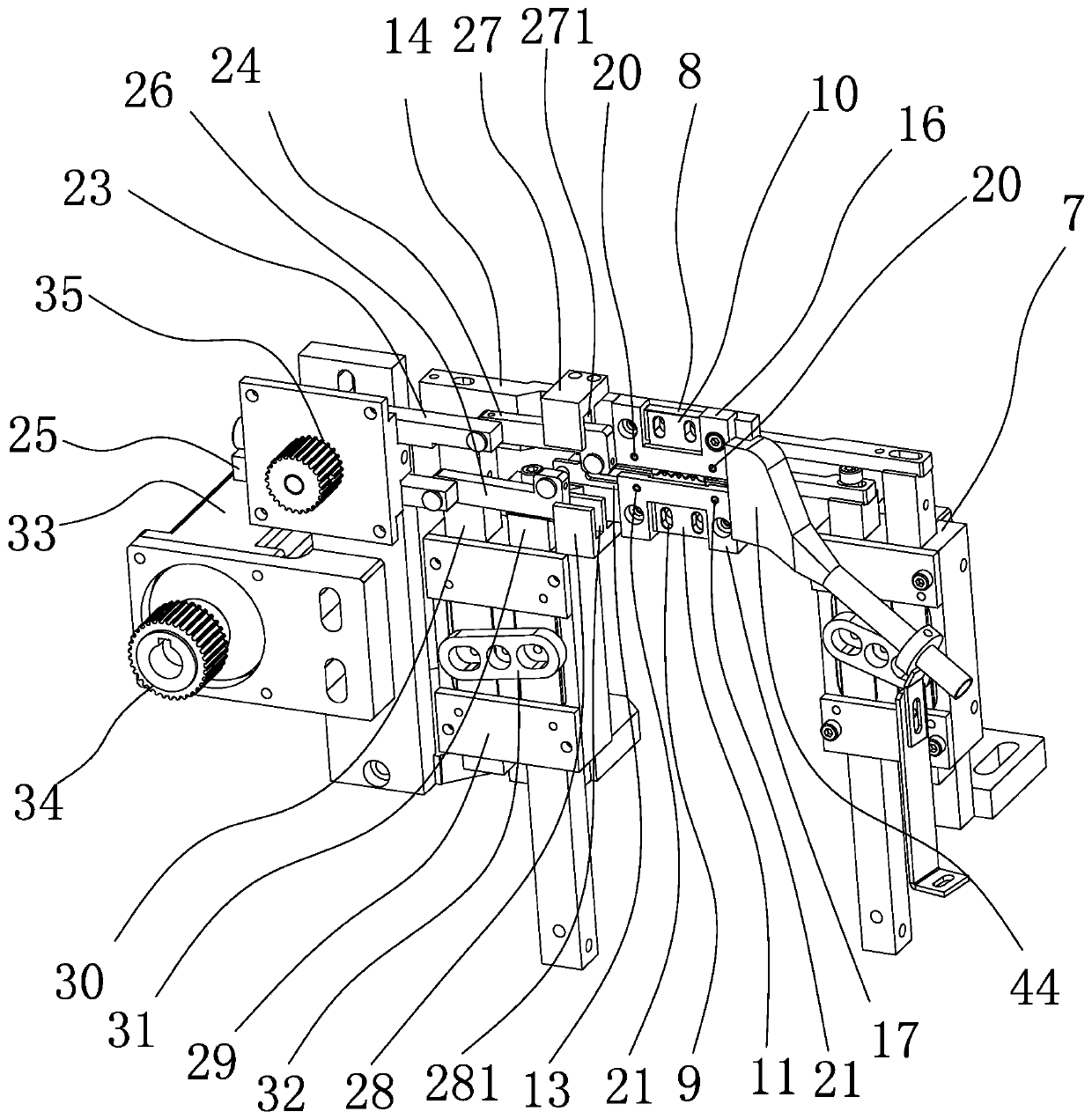
[0031] refer to figure 1 and figure 2 , the present embodiment is a wire cutting, stripping and rubbing device. The wire cutting, stripping and rubbing device is arranged on the workbench 1, and is used to send the wire after cutting, stripping and rubbing to the clamp of the divider turntable 2. This wire cutting and stripping device includes a wire feeding mechanism 3, a wire cutting and stripping mechanism 4, a wire twisting mechanism 5, a tinning mechanism 6 and an auxiliary clamp mechanism 7, wherein the cutting and stripping mechanism 4 and the twisting mechanism 5 are integrated together and simultaneously Carry out wire cutting and stripping operations and wire twisting operations; the wire feeding mechanism 3 in...


PUM


Abstract

The invention provides a lead cutting, stripping and twisting device and a lead cutting, stripping and twisting method, belongs to the mechanical technical field, and solves the problems of cumbersomeoperation steps and poor effect of the existing lead cutting, stripping and twisting and the problems of lack of leg tension and stability of eyeglasses. The lead cutting, stripping and twisting device comprises a lead feeding mechanism and a lead cutting and stripping mechanism. The lead cutting, stripping and twisting device is characterized by further comprising a lead twisting mechanism. Thelead cutting and stripping mechanism comprises a cutter assembly and a stripping cutter assembly. The lead twisting mechanism comprises a lead twisting driving assembly and a lead twisting assembly. The lead twisting assembly is positioned between the cutter assembly and the stripping cutter assembly. The lead cutting, stripping and twisting operation can be realized, the operation time is short and the tinning effect after lead cutting, stripping and twisting is good.

Description

technical field [0001] The invention belongs to the technical field of machinery and relates to a wire cutting, stripping and rubbing device. Background technique [0002] In the electronic component welding machine, it is necessary to connect various electronic components to the wires by welding, and the wires need to be cut and stripped before tinning, but when multi-core wires are used, the wires after stripping directly, The core wire is extremely loose, the effect of tin dipping is not good, and it is easy to desolder. Chinese patent [authorized announcement number: CN 207664431 U] discloses a knife holder mechanism that can cut and strip wires and twist wires, including: knife holder seat, scissors The cutting assembly and the twisting mechanism, the cutting assembly includes first and second cutting knife assemblies slidingly arranged on the knife holder seat, and a shearing drive mechanism capable of driving the first and second cutting knife assemblies to move relat...

Claims


Application Information

Patent Timeline
Patent Type & Authority Applications(China)
IPC IPC(8): H01R43/28
CPCH01R43/28Y02W30/82
Inventor 吴志浩
Owner TAIZHOU HAORAN MACHINERY MFG
Learn More