Centrifugal spinning nozzle system for generating multiple fibers

A centrifugal spinning and multi-fiber technology, which is applied in fiber processing, spinneret assemblies, textiles and papermaking, etc., can solve the problems of low manufacturing efficiency, achieve high manufacturing efficiency, improve manufacturing efficiency, and prevent mutual interference.

Active Publication Date: 2019-10-11
WUHAN TEXTILE UNIV
View PDF5 Cites 2 Cited by
  • Summary
  • Abstract
  • Description
  • Claims
  • Application Information

AI Technical Summary

Problems solved by technology

[0007] The purpose of the present invention is to overcome the defects and problems of low manufacturing efficiency in the

Method used


Image

  • Centrifugal spinning nozzle system for generating multiple fibers
  • Centrifugal spinning nozzle system for generating multiple fibers
  • Centrifugal spinning nozzle system for generating multiple fibers

Examples


Embodiment 1

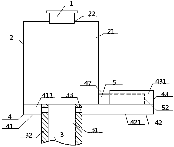
[0047] see Figure 1 to Figure 6 , a centrifugal spinning nozzle system that generates multi-fibers, comprising an injection pipe 1, a spinning head 2 and a driving pipe 3, the bottom of the spinning head 2 is connected to the top of the driving pipe 3, and the spinning head 2 The inside is provided with a material holding chamber 21, and the bottom end of the injection pipe 1 passes through the injection port 22 and communicates with the top of the material holding chamber 21; the centrifugal spinning nozzle system also includes an air receiving shell 4 and a spinning Tube 5, the inside of the spinneret 5 is provided with a spinneret cavity 51, the inner end of the spinneret 5 is connected to the left side of the spinning head 2, the outer end of the spinneret 5 extends outward, and the spinneret The outer end of the tube 5 is provided with a spinneret 52, the spinneret 52 communicates with the material chamber 21 through the spinneret 51, and the number of the spinneret 5 is...

Embodiment 2

[0049] Basic content is the same as embodiment 1, the difference is:

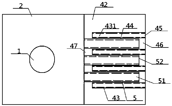
[0050] A spinneret gap 46 is provided between the spinneret 52 and the outer end of the finger holder cavity 44 . The width of the hollow shell finger 43 is smaller than the width of the right hollow shell portion 42 , and a finger gap 47 is provided between the inner end of the hollow shell finger 43 and the left side of the spinning head 2 .

Embodiment 3

[0052] Basic content is the same as embodiment 1, the difference is:

[0053] The inside of the driving tube 3 is provided with a tube lumen 31, and the tube wall 32 located in the left receiving air cavity 411 on the driving tube 3 is provided with a side air passage 33, and the tube lumen 31 connects with the left receiving air cavity 411 through the side air passage 33. connected. The number of the side air passages 33 is four, and all the side air passages 33 are evenly arranged around the tube wall 32 , and the top view shape of the side air passages 33 is fan-shaped.


PUM


Abstract

The invention relates to a centrifugal spinning nozzle system for generating multiple fibers. The system comprises a material injection pipe, a spinning head, a driving pipe, an air containing hollowshell and at least two silk spraying pipes, wherein a material containing cavity is formed in the spinning head, silk spraying cavities are formed in the silk spraying pipes, the inner ends of the silk spraying pipes are connected with the side part of the spinning head, and silk spraying openings are formed in the outer ends of the silk spraying pipes and communicated with the material containingcavity through the silk spraying cavities; the air containing hollow shell comprises a left hollow shell part, a right hollow shell part and multiple empty shell fingers; a left air containing cavity, a right air containing cavity and air containing finger cavities are formed in the left hollow shell part, the right hollow shell part and the empty shell fingers respectively; a finger clamping cavity is formed between every two adjacent empty shell fingers, the corresponding silk spraying pipe is clamped in each finger clamping cavity, and air outlets communicated with the air containing finger cavities are formed in the outer side faces of the empty shell fingers. According to the design, not only is the manufacturing efficiency high, blockage is unlikely to happen, but also the guiding property is excellent, and the liquid state of a liquid material can be ensured.

Description

technical field [0001] The invention relates to a production device for superfine fibers, which belongs to the field of nanofiber manufacturing, and in particular to a centrifugal spinning nozzle system for generating multi-fibers, which is particularly suitable for improving manufacturing efficiency and is not prone to blockage. Background technique [0002] Nanofibers refer to ultrafine fibers with a diameter of tens to hundreds of nanometers, which have unique advantages that other fibers cannot possess, such as very large specific surface area, ultrafine porosity, and good mechanical properties. In recent years, nanofibers have been widely used in textile materials, tissue engineering scaffolds, drug delivery, filter media, artificial blood vessels, biochips, nanosensors, optics, composite materials and other fields. [0003] So far, there are many methods for preparing nanofibers, such as stretching, microphase separation, template synthesis, self-assembly, electrospinn...

Claims


Application Information

Patent Timeline
IPC IPC(8): D01D4/02D01D5/18D01D10/02
CPCD01D4/02D01D5/18D01D10/02
Inventor 张智明张彪徐巧梅顺齐姬巧玲肖人彬
Owner WUHAN TEXTILE UNIV
Why Eureka
Try Eureka