
Dry-hot rock high-energy hydraulic dynamic down-the-hole hammer spraying and reaming device

A technology of hydraulic down-the-hole hammer and hot dry rock, which is applied to the valve device of borehole/well, drilling with liquid/gas jet, borehole/well parts, etc., which can solve the problems of low drilling efficiency and hot dry rock drilling. Improve drilling efficiency, save time and drilling costs, and reduce drilling and reaming operations and lifting operations

Pending Publication Date: 2019-10-11
JILIN UNIV +1
View PDF0 Cites 2 Cited by
  • Summary
  • Abstract
  • Description
  • Claims
  • Application Information

AI Technical Summary

Problems solved by technology

[0005] The purpose of the present invention is to solve the problem that in the existing hot dry rock drilling process, the roller cone bit needs to be lowered to ream each time after replacing a new down-the-hole hammer bit, which leads to an increase in the cost of dry hot rock drilling and low drilling efficiency. Provides a new type of reliable hot dry rock high-energy hydraulic DTH hammer jet reaming device for reducing drilling costs and improving drilling efficiency

Method used


Image

  • Dry-hot rock high-energy hydraulic dynamic down-the-hole hammer spraying and reaming device
  • Dry-hot rock high-energy hydraulic dynamic down-the-hole hammer spraying and reaming device

Examples


Embodiment Construction

[0026] In order to illustrate the present invention more clearly, the present invention will be further described below in conjunction with preferred embodiments and accompanying drawings. It should be understood by those skilled in the art. The content specifically described below is illustrative rather than restrictive, and should not limit the protection scope of the present invention.

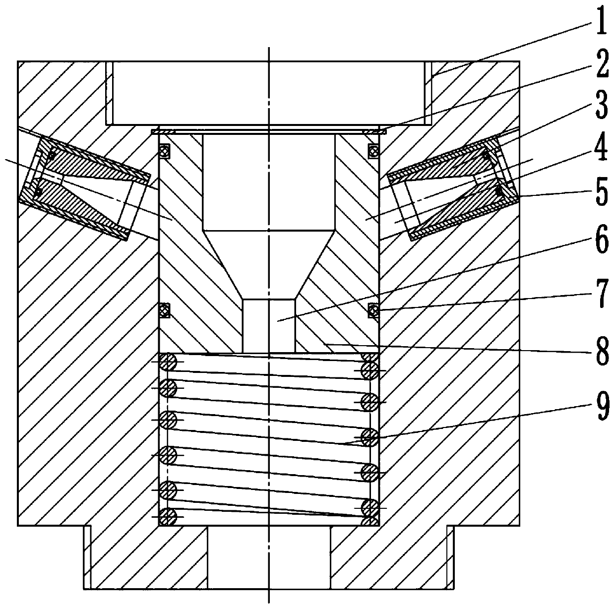
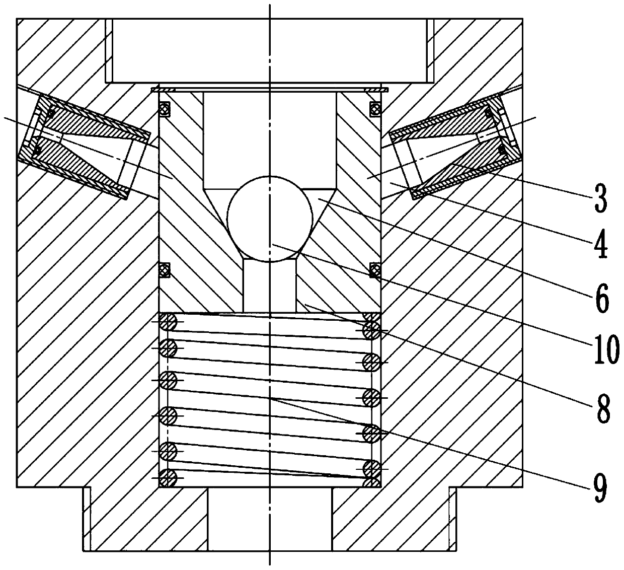
[0027] Such as figure 1 and figure 2 As shown, the hot dry rock high-energy hydraulic down-the-hole hammer jet reaming device includes an outer tube 1, a retaining ring 2, a nozzle 3, a water jet channel 4, a nozzle cover 5, a down-the-hole hammer liquid flow channel 6, and a sealing ring 7 , valve seat 8, spring 9 and steel ball 10, the upper end of the outer pipe 1 is threadedly connected with the drill pipe, the lower end of the outer pipe 1 is threaded with the hydraulic down-the-hole hammer, the outer pipe 1, the drill pipe and the hydraulic The down-the-hole hammer is arranged coa...


PUM


Abstract

The invention relates to a dry-hot rock high-energy hydraulic dynamic down-the-hole hammer spraying and reaming device and belongs to the technical field of dry-hot rock drilling tools. The dry-hot rock high-energy hydraulic dynamic down-the-hole hammer spraying and reaming device comprises an outer pipe, an elastic check ring, a nozzle, a water jet flow channel, a nozzle sleeve, a down-the-hole hammer liquid flow channel, a valve seat, a spring and a steel ball. The upper end of the outer pipe is in threaded connection with a drill rod. The lower end of the outer pipe is in threaded connection with a hydraulic down-the-hole hammer. The steel ball is used for controlling the opening and the closing of the water jet flow channel and the down-the-hole hammer liquid flow channel. During drilling operation, the steel ball is not placed in the down-the-hole hammer liquid flow channel, the drill rod, the outer pipe and the central liquid flow channel of the hydraulic down-the-hole hammer communicate with each other, and water flow of the water jet flow channel is separated by the upper portion of the valve seat. When drilling is completed and a down-the-hole hammer drill bit needs to bereplaced with a new down-the-hole hammer drill bit, the steel ball is placed in the down-the-hole hammer liquid flow channel, the down-the-hole hammer liquid flow channel is closed, the water jet flowchannel is opened, drilling fluid passes through the nozzle to form a water jet flow for crushing hole wall rock, and reaming is realized. According to the dry-hot rock high-energy hydraulic dynamicdown-the-hole hammer spraying and reaming device, reaming is completed while extraction is carried out, the time cost and the drilling cost are saved, and the dry-hot rock drilling efficiency is improved.

Description

technical field [0001] The invention relates to the technical field of drilling tools for hot dry rock drilling, in particular to a jet reaming device for hot dry rock high-energy hydraulic down-the-hole hammer. Background technique [0002] Geothermal energy is a clean energy that is widely distributed, abundant in reserves, renewable, non-polluting, and has great potential for development. Compared with hydrothermal geothermal resources, more geothermal energy is stored in underground high-temperature rock masses with no or little water to form hot dry rock geothermal resources. At the same time, because geothermal resources are contained in hot dry rocks, the research on related hot dry rock drilling and development technologies is very important for the development of geothermal resources. [0003] Since hot dry rock formations are usually igneous rocks, which have the characteristics of deep burial, poor drillability, and strong abrasiveness, drilling is a key link in ...

Claims


Application Information

Patent Timeline
Patent Type & Authority Applications(China)
IPC IPC(8): E21B7/28E21B7/18E21B34/06
CPCE21B7/28E21B7/18E21B34/06E21B2200/04
Inventor 彭枧明杨正龙李宽李彦良李柯柯张广张鹏宇
Owner JILIN UNIV
Learn More