Railway vehicle air resistance calculation method based on numerical simulation

A rail vehicle, numerical simulation technology, applied in the direction of calculation, electrical digital data processing, special data processing applications, etc., can solve the problems of large errors in the calculation formula of air resistance, inability to guide power matching, and inapplicable air resistance of rail vehicles, etc., to achieve Optimized aerodynamic performance and improved accuracy

Active Publication Date: 2019-10-11
CRRC QINGDAO SIFANG ROLLING STOCK RES INST
View PDF11 Cites 4 Cited by
  • Summary
  • Abstract
  • Description
  • Claims
  • Application Information

AI Technical Summary

Problems solved by technology

However, in the existing air resistance calculation methods, the wind tunnel test and coasting test have certain limitations. Usually, after the development of the vehicle model is completed, the test is carried out on the existing vehicle model, which cannot guide the power matching in the early development process of the vehicle model. ; and the existing air resistance calculation formula has a large error, which is generally applicable to long and small vehicles such as cars. The air resistance calculation is only related to air density, windward area, running speed and front shape, and does not reflect important factors such as vehicle length. Therefore, it is impossible to directly calculate the air resistance of rail vehicles
[0003] Therefore, the existing wind tunnel test and coasting test are not suitable for the calculation of the air resistance of rail vehicles. It is necessary to design a calculation method for the air resistance of rail vehicles considering the influence of factors such as vehicle length and vehicle type.

Method used


Image

  • Railway vehicle air resistance calculation method based on numerical simulation
  • Railway vehicle air resistance calculation method based on numerical simulation
  • Railway vehicle air resistance calculation method based on numerical simulation

Examples


Embodiment Construction

[0035] Specific embodiments of the present invention will be further described below in conjunction with the accompanying drawings.

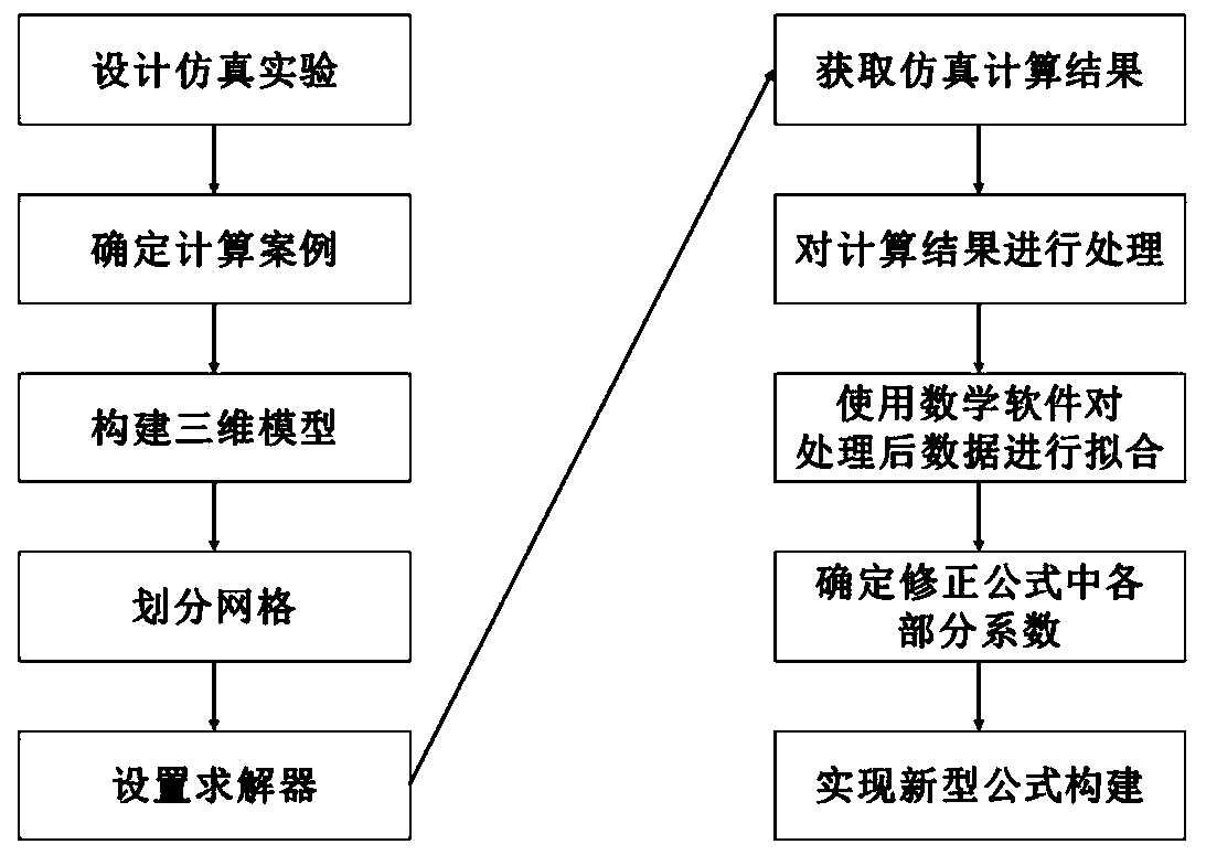
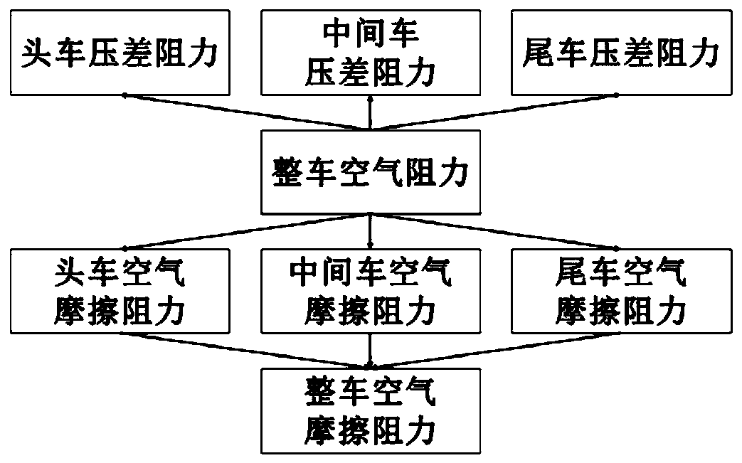
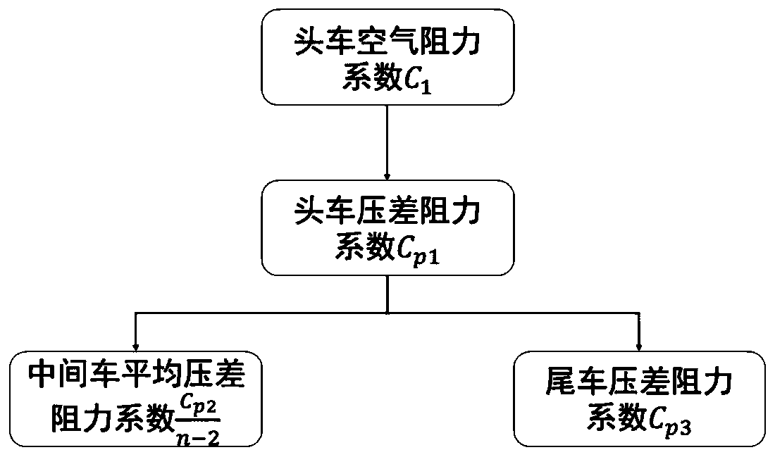
[0036] The present invention provides a method for calculating the air resistance of rail vehicles based on numerical simulation for the calculation of air resistance of rail vehicles. figure 1 , figure 2 , image 3 shown, including the following steps:

[0037] (S1) Establish the experimental model required for numerical simulation and divide the grid: namely

[0038] ①Establish the three-dimensional model of the rail vehicle and the three-dimensional model of the surrounding flow field space;

[0039] Specifically, in this embodiment, three-dimensional drawing software is used to construct the required experimental models of the two vehicle types A and B. The front of the urban rail type A car is 3m wide and 3.8m high; the front car of the urban rail type B car is 2.8m wide and 3.8m high. Considering the design size of the joint between ...


PUM


Abstract

The invention relates to a railway vehicle air resistance calculation method based on numerical simulation. The method comprises the steps that a model needed by numerical simulation is established, and grids are divided; analogue simulation is performed, the air resistance coefficient of the vehicle is corrected according to the air pressure difference resistance and the air friction resistance of the rail vehicle; and according to the corrected vehicle air resistance coefficient, a vehicle air resistance rapid calculation formula is constructed and the vehicle air resistance rapid calculation formula is verified. According to the method, numerical simulation calculation is carried out on the numerical value of the air resistance borne by a common rail vehicle model moving under typical working conditions, calculation of the middle vehicle differential pressure resistance, the tail vehicle differential pressure resistance and the whole vehicle air friction resistance is added, and thevehicle air resistance coefficient is corrected. Defects in an existing air resistance calculation formula are overcome, and the accuracy of the air resistance calculation formula is improved, so that the air resistance calculation formula is suitable for vehicles with large slenderness ratios, such as railway vehicles.

Description

technical field [0001] The invention belongs to the technical field of vehicle air resistance calculation, in particular to a numerical simulation-based calculation method for rail vehicle air resistance. Background technique [0002] The level of traction energy consumption is closely related to the resistance of rail vehicles. When a vehicle is running, one of the resistances to be overcome is air resistance. As the vehicle speed increases, air resistance gradually becomes the most important driving resistance. Appropriate vehicle air resistance calculation methods are very important for analyzing the running conditions and vehicle performance of rail vehicles, as well as the later improvement of rail vehicles. However, in the existing air resistance calculation methods, the wind tunnel test and coasting test have certain limitations. Usually, after the development of the vehicle model is completed, the test is carried out on the existing vehicle model, which cannot guid...

Claims


Application Information

Patent Timeline
IPC IPC(8): G06F17/50
CPCG06F30/15G06F2119/06Y02T90/00
Inventor 张辉孙国斌李政达宫保贵孙丛君李家兴
Owner CRRC QINGDAO SIFANG ROLLING STOCK RES INST
Why Eureka
Try Eureka