Cabin structure of aircraft, aircraft and flying car

A technology of flying cars and aircraft, applied in the field of aircraft, can solve the problems of complex structure of the aircraft cabin, large space and heavy weight of the aircraft, and achieve the effects of weight saving, reasonable space layout, and convenient disassembly and maintenance process

Active Publication Date: 2019-10-15
COOL HIGH TECH BEIJING CO LTD
View PDF10 Cites 0 Cited by
  • Summary
  • Abstract
  • Description
  • Claims
  • Application Information

AI Technical Summary

Problems solved by technology

[0006] The above design leads to a more complex cabin structure of the aircraft, which indirectly leads to large space and heavy weight of the aircraft.

Method used


Image

  • Cabin structure of aircraft, aircraft and flying car
  • Cabin structure of aircraft, aircraft and flying car
  • Cabin structure of aircraft, aircraft and flying car

Examples


Embodiment 1

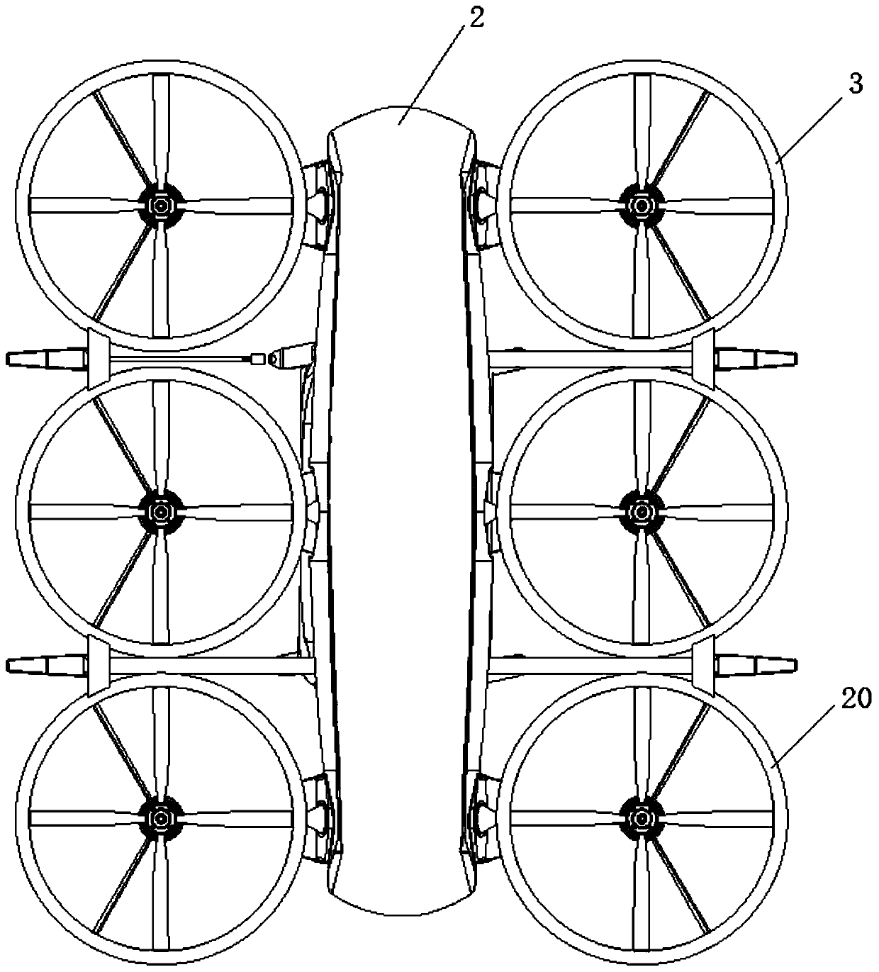
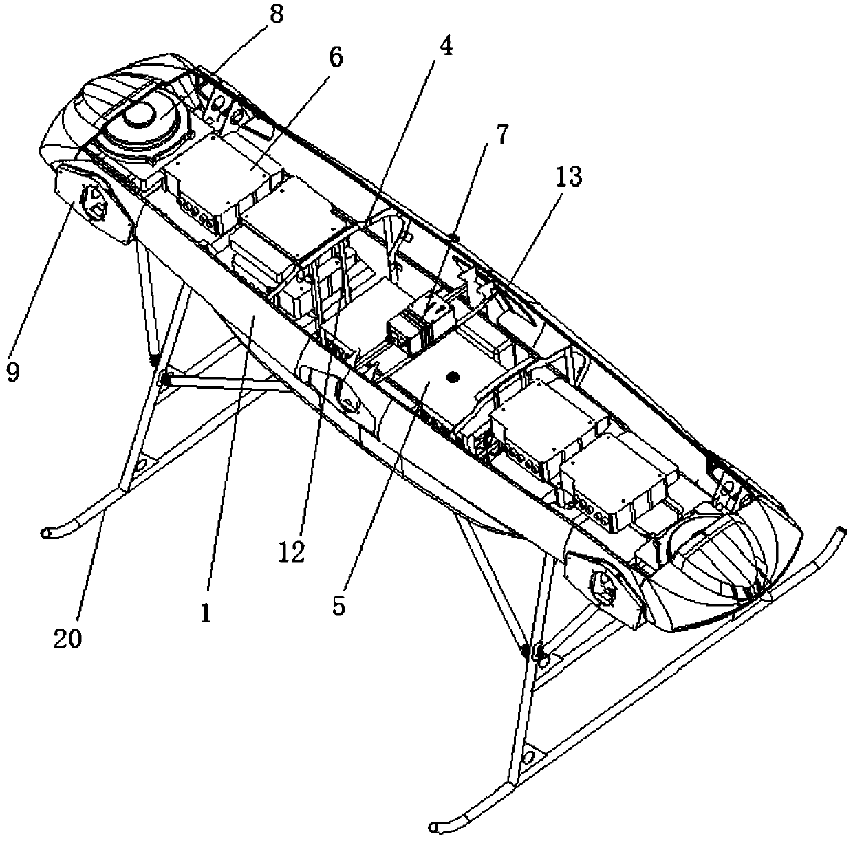
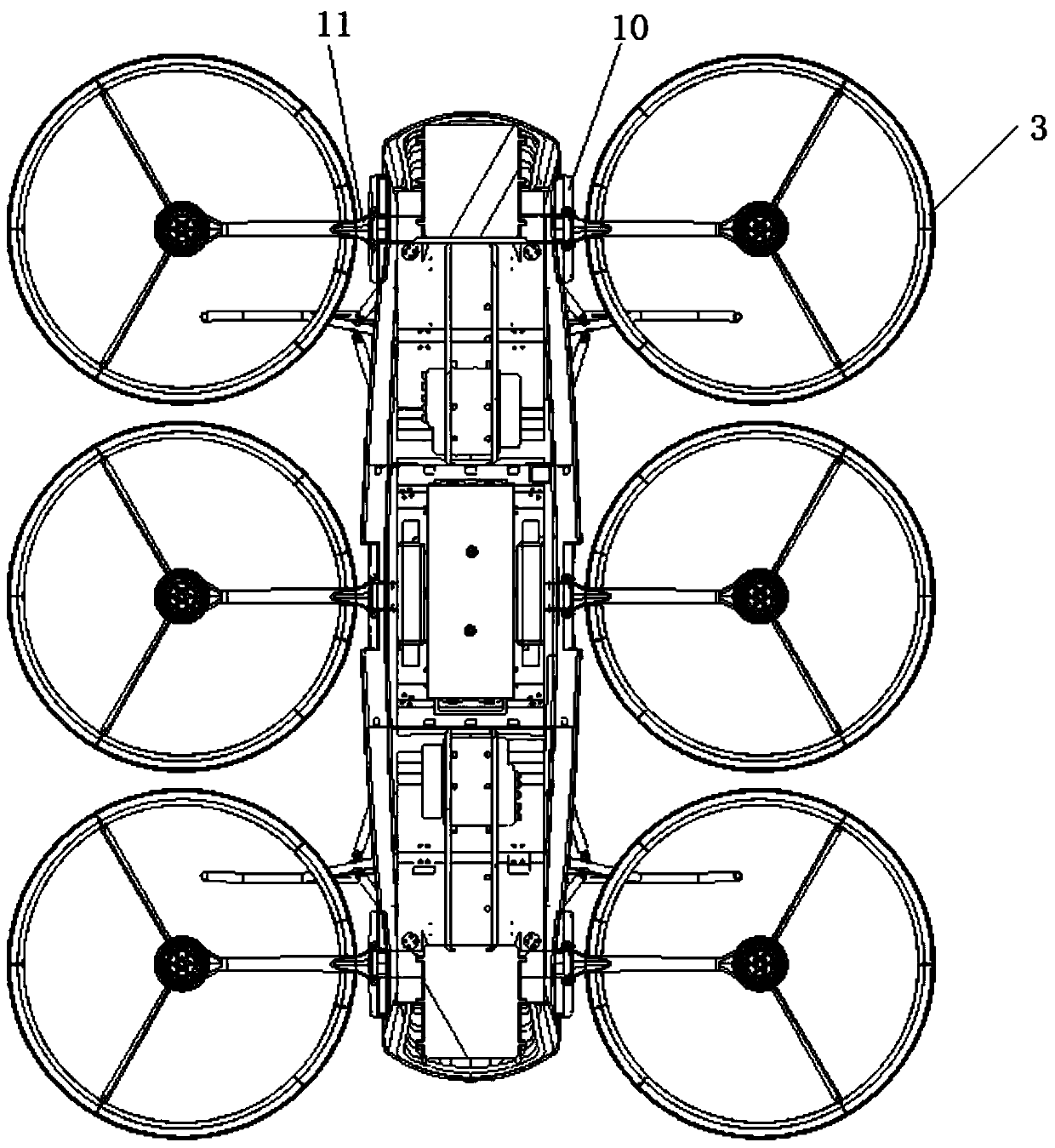
[0034] Embodiment 1, see attached figure 1 , 2 , a cabin structure of an aircraft, which comprises: a cabin shell 1, a hatch cover 2, a power unit 3 symmetrically arranged on both sides of the cabin shell 1, a partition frame 4, a battery pack 5 are arranged in the cabin shell 1 , motor controller 6, flight control device 7 and cooling device 8.

[0035] The nacelle shell 1 is a horizontally and vertically symmetrical structure, preferably elongated, with a streamlined aerodynamic shape; the top of the nacelle shell 1 is provided with a large-span hatch; the hatch cover 2 is arranged at the hatch; The bottom also can be provided with landing gear 20.

[0036] The power plant 3 includes at least two ducts or rotors distributed on the outer periphery of the nacelle shell 1; the number of ducts or rotors is an even number, which can be symmetrically distributed on the left and right sides of the elongated nacelle shell 1, usually four Duct or rotor can meet the requirements of...

Embodiment 2

[0042] Embodiment 2, on the basis of Embodiment 1, the cabin shell 1 is further limited:

[0043] The cabin is a semi-monocoque structure. The semi-monocoque structure includes a partial skeleton and a cabin shell 1 capable of bearing force. The strength of the semi-monocoque structure meets the requirements of use, and the quality is not too heavy, which reduces energy consumption. . The cabin shell 1 adopts a honeycomb sandwich structure, that is, a honeycomb core material is provided between the inner and outer skins, and the skin and the honeycomb core material are connected by curing; the honeycomb core material can be made of paper or aluminum. In this example, the honeycomb core material is preferably paper, the thickness of the honeycomb core material is 4-15 mm, and the thickness of the skin is 0.4-1 mm. According to the rigidity and strength requirements of different positions, honeycomb core materials with different thickness specifications can be used in different...

Embodiment 3

[0046] Embodiment 3, on the basis of embodiment 1 or 2, the described bulkhead 4 is further limited:

[0047] See attached figure 2 , in this example, the bulkhead 4 is an inverted U-shaped structure, and is arranged at the hatch position, and is close to the front and rear ends of the hatch respectively, forming reinforcement at the hatch, which makes up for the gap caused by the opening of the hatch on the cabin shell 1. Strength weakening and structural deformation. Furthermore, in this example, four bracket columns 12 are symmetrically arranged in each bulkhead 4; one end of the bracket column 12 is fixedly connected with the bottom plate of the cabin shell 1, and the other end is fixedly connected with the bulkhead 4; The frame column 12 strengthens the frame 4, supports each other through the frame 4 and the frame column 12 to form a support frame, increases the stability of the frame 4 and the rigidity of the engine room, and meets the support requirements for each eq...


PUM


Abstract

The invention relates to the technical field of aircraft and discloses a cabin structure of an aircraft. The cabin structure of the aircraft comprises a cabin shell, a hatch cover, power devices, a partition frame, a battery pack, heat radiation devices, motor controllers and a flight control device, wherein the power devices are symmetrically arranged on the two sides of the cabin shell; the partition frame is used for supporting the cabin shell and performing section division on the interior of the cabin shell; the battery pack is fixedly arranged at the middle part of the cabin shell; the heat radiation devices are arranged at the front and rear ends of the cabin shell; the motor controllers are arranged close to the power devices; the flight control device is arranged far away from themotor controllers. According to the cabin structure of the aircraft, through integrated design of a power compartment and an equipment compartment, the power cabin is prevented from being singly arranged; as the heat radiation devices and the motor controllers are arranged at the front part and the rear part of the cabin and are far away from the flight control device arranged at the middle partof the cabin, electromagnetic interference is avoided; and the cabin structure of the aircraft has the advantages that the weight is saved and the space layout is reasonable. Meanwhile, the inventionfurther discloses an aircraft including the cabin structure and a flying car.

Description

technical field [0001] The invention relates to the technical field of aircraft, in particular to an aircraft cabin, an aircraft and a flying car adopting the cabin structure. Background technique [0002] In the prior art, the cabin of an aircraft includes: an independent power cabin, an equipment cabin and an isolation cabin. [0003] Since power equipment such as an engine, clutch and reduction box needs to be installed in the power cabin, the power cabin must be equipped with a strong system hanger and a shock absorber, and a good sound insulation effect should also be provided. [0004] The equipment cabin is divided into several independent spaces according to the functions, and the auxiliary power system, life-saving equipment, emergency equipment and other functional components are placed in the space; the equipment cabin needs to maintain low temperature and low noise and vibration. [0005] Flight control, navigation and positioning systems, airborne data terminal...

Claims


Application Information

Patent Timeline
Patent Type & Authority Applications(China)
IPC IPC(8): B64D27/24B64D27/26B64D33/10B64C1/00B64C1/14B60F5/02
CPCB64D27/24B64D27/26B64D33/10B64C1/00B64C1/14B60F5/02Y02T50/40
Inventor 高学勤马罡徐彬刘春桃孙博
Owner COOL HIGH TECH BEIJING CO LTD
Why Eureka
Try Eureka