Red phosphorescent compound, and organic luminescent devices prepared from red phosphorescent compound

A technology of red phosphorescence and compounds, applied in the direction of luminescent materials, organic chemistry, electric solid devices, etc., can solve the problems of complex manufacturing process, low process efficiency, no solubility, etc., achieve excellent color purity and brightness, and prolong durability Effect

Active Publication Date: 2019-10-15
ZHEJIANG HUADISPLAY OPTOELECTRONICS CO LTD
View PDF9 Cites 2 Cited by
  • Summary
  • Abstract
  • Description
  • Claims
  • Application Information

AI Technical Summary

Problems solved by technology

However, these compounds do not have ideal solubility in solvents and thus cannot be used to form the light-emitting layer by solution process
The light-emitting layer should be formed by a deposition proc

Method used


Image

  • Red phosphorescent compound, and organic luminescent devices prepared from red phosphorescent compound
  • Red phosphorescent compound, and organic luminescent devices prepared from red phosphorescent compound
  • Red phosphorescent compound, and organic luminescent devices prepared from red phosphorescent compound

Examples


Embodiment 1

[0076] The ITO glass substrate was patterned to have a light emitting area of ​​3 mm x 3 mm. Then, the patterned ITO glass substrate was washed.

[0077] The substrate is then placed in a vacuum chamber. The standard pressure setting is 1×10 -6 support. Thereafter, on the ITO substrate with CuPc NPB RH-001+(mxmq)2Ir(acac)((5%) Alq3 LiF and Al The sequence forms layers of organic matter.

[0078] At 0.9mA, the brightness is equal to 1248d / m 2 (5.0V). At this time, CIEx=0.657, y=0.329.

Embodiment 2

[0080] The ITO glass substrate was patterned to have a light emitting area of ​​3 mm x 3 mm. Then, the patterned ITO glass substrate was washed.

[0081] The substrate is then placed in a vacuum chamber. The standard pressure setting is 1×10 -6 support. Thereafter, on the ITO substrate with CuPc NPB RH-007+(mxmq)2Ir(acac)(5%) Alq3 LiF and Al The sequence forms layers of organic matter.

[0082] At 0.9mA, the brightness is equal to 1293cd / m 2 (5.3V). At this time, CIEx=0.657, y=0.330.

Embodiment 3

[0084] The ITO glass substrate was patterned to have a light emitting area of ​​3 mm x 3 mm. Then, the patterned ITO glass substrate was washed.

[0085] The substrate is then placed in a vacuum chamber. The standard pressure setting is 1×10 -6 support. Thereafter, on the ITO substrate with CuPc NPB RH-082+(mxmq) 2 Ir(acac)(5%) Alq 3 LiF and Al The sequence forms layers of organic matter.

[0086] At 0.9mA, the brightness is equal to 1261cd / m 2(5.1V). At this time, CIEx=0.658, y=0.329.


PUM


Abstract

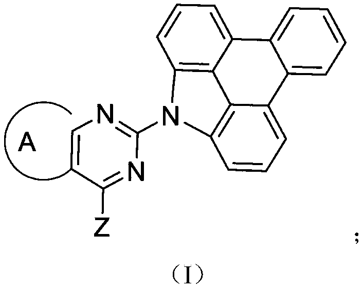
The invention relates to a red phosphorescent compound, and organic luminescent devices prepared from the red phosphorescent compound, and more specially relates to a soluble phosphorescent compound high in color purity, brightness, and luminescent efficiency, and OLED devices using the soluble phosphorescent compound. The structure formula of the red phosphorescent compound is disclosed by formula I in the invention, wherein Z is used for representing a structure independently selected from structures disclosed in the invention, Ar is used for representing one structure independently selectedfrom C6-30 aryl, and C2-30 heteroaryl, A is used for representing one structure independently selected from benzene, naphthalene, phenanthrene, and triphenylene; the C6-30 aryl is one selected from phenyl, naphthyl, terphenyl, and phenanthryl; and C2-30 heteroaryl is one selected from pyridyl, dipyridyl, quinolyl, isoquinolyl, phenanthrolinyl, and triazinyl. The compound represented by formula (I) is adopted to prepare a luminescent layer of oganic light emitting diodes, and excellent color purity, brightness, and prolonged durability effect are achieved.

Description

technical field [0001] The present invention relates to a red phosphorescent compound and an organic light-emitting device using the compound, more specifically, to a soluble phosphorescent compound having excellent color purity and high brightness and luminous efficiency and an OLED device using the compound. Background technique [0002] Recently, demand for flat panel displays such as liquid crystal displays and plasma display panels is increasing. However, these flat panel displays have slower response times and narrower viewing angles than cathode ray tubes (CRTs). Organic Light Emitting Diode (OLED) devices are one of the next-generation flat panel displays that can solve the above problems and occupy a smaller footprint. Components of OLED devices can be formed on flexible substrates, such as plastic substrates. In addition, OLED devices have advantages in viewing angle, driving voltage, power consumption, and color purity. On the other hand, OLED devices are suffi...

Claims


Application Information

Patent Timeline
IPC IPC(8): C07D401/14C07D403/14C07D471/04C09K11/06H01L51/54
CPCC07D403/14C07D401/14C07D471/04C09K11/06C09K2211/1029C09K2211/1044C09K2211/1059C09K2211/1007C09K2211/1011H10K85/615H10K85/622H10K85/654H10K85/6572
Inventor 高春吉汪华月叶绪兵
Owner ZHEJIANG HUADISPLAY OPTOELECTRONICS CO LTD
Why Eureka
Try Eureka