Heat accumulating type flue gas recirculation combustion nozzle and combustion system

A flue gas recirculation, regenerative technology, applied in the combustion chamber, combustion method, combustion type, etc., can solve the problem of single combustion method, large amount of pollutants such as NOx, difficult to meet environmental protection standards, and low energy utilization rate of burners and other problems, to achieve the effect of reducing combustion temperature, reducing concentration, and reducing NOx generation

Active Publication Date: 2019-10-15
秦皇岛鸿泰科技股份有限公司
View PDF9 Cites 0 Cited by
  • Summary
  • Abstract
  • Description
  • Claims
  • Application Information

AI Technical Summary

Problems solved by technology

[0002] At present, the energy utilization rate of traditional burners is low, the combustion method is single, and th

Method used


Image

  • Heat accumulating type flue gas recirculation combustion nozzle and combustion system
  • Heat accumulating type flue gas recirculation combustion nozzle and combustion system
  • Heat accumulating type flue gas recirculation combustion nozzle and combustion system

Examples


Embodiment 1

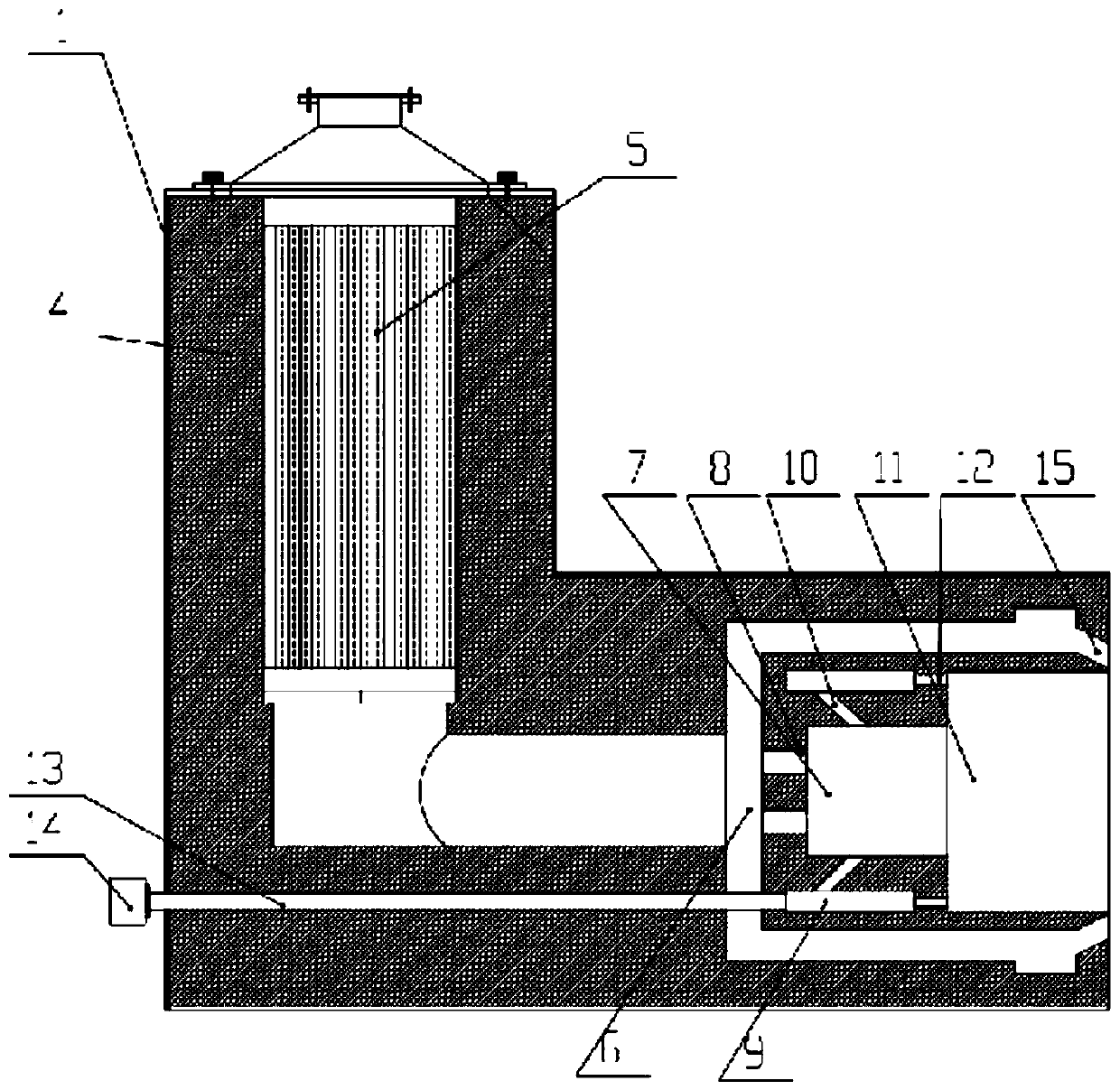
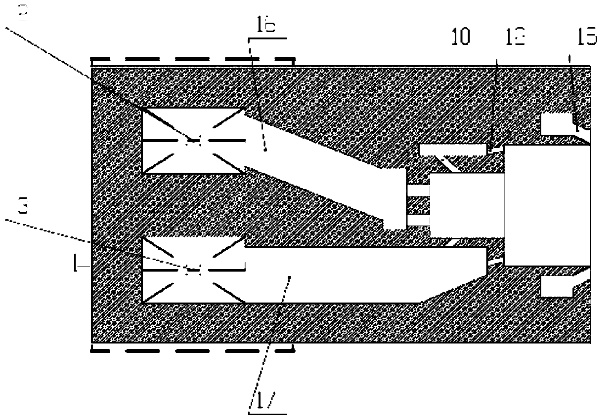
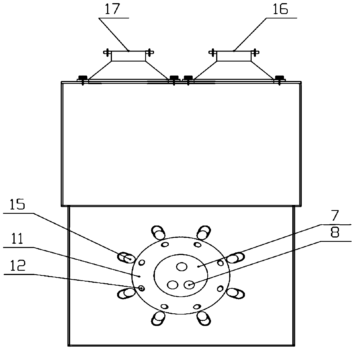
[0035] see Figure 1-Figure 3 , a regenerative flue gas recirculation burner in this embodiment, including a gas heat storage box 2, an air heat storage box 3, a primary combustion chamber 7 and a secondary combustion chamber 11, after the gas passes through the gas heat storage box 2 It flows through the gas channel 16 and enters the gas classification channel 6, the air passes through the air heat storage tank 3 and then flows through the air flue gas channel 17 and enters the air classification channel 9, and the gas and air enter the first level, In the secondary combustion chamber and the hearth of the industrial furnace; the air classification channel 9 is connected with a flue gas recirculation channel 13, which is used to further pass the flue gas generated after combustion into the burner for combustion, and finally achieve the purpose of multi-stage combustion.

[0036] The gas classification passage 6 communicates with the primary combustion chamber 7 through the pr...

Embodiment 2

[0043] The structure in this embodiment is basically the same as that of Embodiment 1, except that the acute angle between the swirl air hole and the tangential direction of the circle is 60°, the acute angle between the secondary gas hole and the horizontal direction is 45°, and the swirl flow The gas hole and the secondary gas hole are square column holes, and a plurality of heat storage balls are arranged in the heat storage box.

[0044] According to the design idea of ​​the present invention, in addition to the above-mentioned structure, the inclination angle of the swirl air hole and the secondary gas hole can also be adjusted according to the actual situation; the heat storage box can also be composed of a plurality of honeycomb heat storage bodies and heat storage balls; in addition , the number of primary gas holes, combustion-supporting air holes, swirl air holes and secondary gas holes can also be adjusted according to specific combustion conditions; the number of pr...


PUM


Abstract

The invention discloses a heat accumulating type flue gas recirculation combustion nozzle. The heat accumulating type flue gas recirculation combustion nozzle comprises heat accumulating boxes and atleast two stages of combustion chambers, and fuel gas and air penetrate through the heat accumulating boxes and then enter the combustion chambers; a fuel gas classifying channel and an air classifying channel are arranged between the heat accumulating boxes and the combustion chambers; and a plurality groups of flue gas recirculation channels are connected to the air classifying channel and usedfor further introducing flue gas generated after combustion into the combustion nozzle to be combusted. Through the combustion nozzle structure integrating the heat accumulating boxes, the multiple stages of combustion chambers and the flue gas recirculation channels, the fuel gas and the air enter the staged combustion chambers after absorbing heat of the heat accumulating boxes, waste heat generated by the flue gas is fully utilized, and energy saving and consumption reducing are achieved; the fuel gas and the air are introduced into the multiple stages of combustion chambers in a classifying manner, therefore, the combustion temperature is lowered, and generation of NOx is reduced; and through the flue gas forced back-blowing and recirculating design, multi-stage combustion is further achieved, and the diversified combustion states of the fuel gas at different stages meet the requirements of state environmental protection for the emission level of NOx in the flue gas.

Description

technical field [0001] The invention relates to the technical field of regenerative heating furnaces, in particular to a regenerative flue gas recirculation burner and a combustion system. Background technique [0002] At present, the energy utilization rate of traditional burners is low, the combustion method is single, and the amount of pollutants such as NOx is relatively large, so it is difficult to meet environmental protection standards. How to effectively control the generation and emission of NOx, and then improve the quality of atmospheric environment is one of the important problems to be solved urgently in today's society. At the same time, increasingly stringent environmental regulations require the development of advanced technologies to reduce emissions of pollutants such as NOx. Therefore, low NOx combustion technology is of great significance to my country's energy saving and emission reduction. [0003] Low NOx combustion technology is to improve the combu...

Claims


Application Information

Patent Timeline
IPC IPC(8): F23C6/04F23C9/06F23C3/00F23L15/04
CPCF23C3/006F23C6/042F23C9/06F23C2201/20F23L15/04Y02E20/34
Inventor 公丕学吕鑫刘海宾
Owner 秦皇岛鸿泰科技股份有限公司
Why Eureka
Try Eureka