Multi-path switch quantity scanning detection system

A multi-channel switching and scanning detection technology, which is applied in the detection and control fields, can solve the problems of cumbersome and complicated on-site wiring, increased cost and volume, and no special application, and achieve the effects of small size, long transmission distance and low cost

Pending Publication Date: 2019-10-15
陕西高科电力电子有限责任公司
View PDF0 Cites 0 Cited by
  • Summary
  • Abstract
  • Description
  • Claims
  • Application Information

AI Technical Summary

Problems solved by technology

At present, some data acquisition cards or corresponding digital expansion modules on the market can realize the basic switch signal detection requirements, but there is no special application for real-time detection of dozens or even hundreds of switch signals, and With the increase in the number of detection channels, the cost and volume are greatly increased, and the field wiring is also cumbersome and complicated
On the other hand, when the switching value is transmitted over a long distance, it is susceptible to external electromagnetic interference, resulting in distortion or distortion of the transmission signal; and the switching value is connected to the microprocessor through a long cable at one end. Due to the line impedance and voltage drop of the cable, limits the distance of the cable

Method used


Image

  • Multi-path switch quantity scanning detection system
  • Multi-path switch quantity scanning detection system
  • Multi-path switch quantity scanning detection system

Examples


Embodiment Construction

[0023] The present invention will be described in further detail below in conjunction with the accompanying drawings.

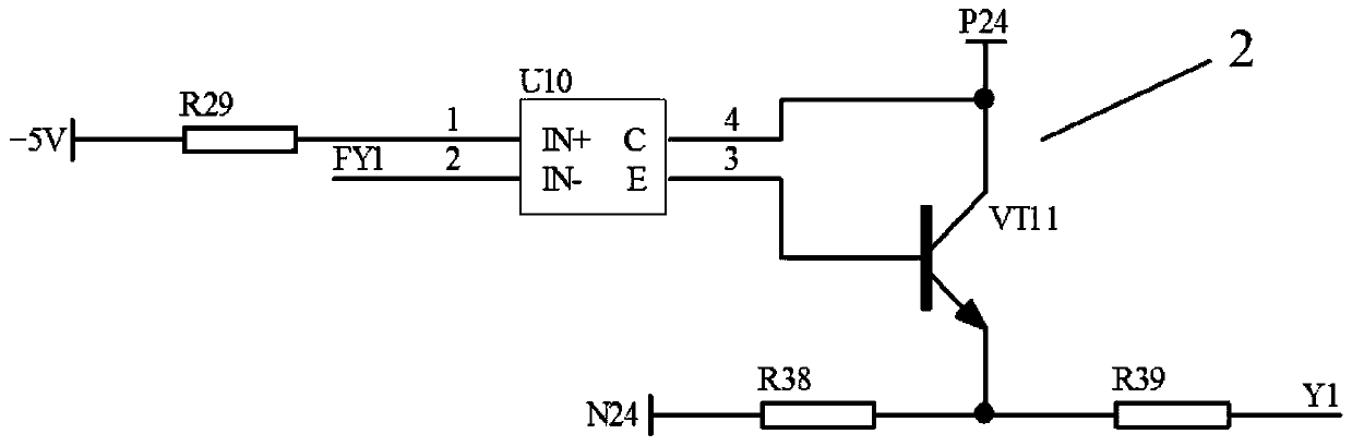
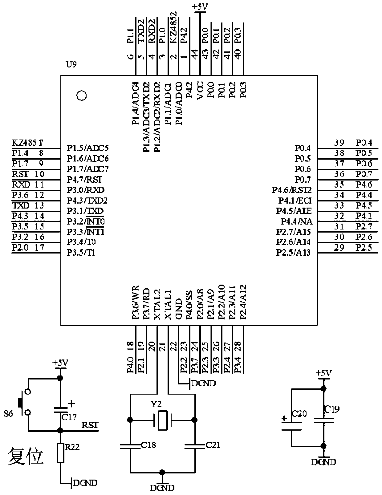
[0024] like Figure 7 As shown, the present invention provides a multi-channel switching value scanning detection system, including a detection control unit 3, the detection control unit 3 is connected with the input filter, isolation, shaping circuit and 1 output isolation, and the drive circuit 2, so that the input and output ports Work in a scanning mode, round-robin detection of the state of each switching value, and process the detection results, while the detection control unit 3 is connected to the switching value position display circuit 4 to display the row and column position of the switching value action, and connected to the RS232 serial port communication circuit 5 , realize the communication function with the host computer, connect with two 485 communication circuits 6, respectively realize the communication function of cascading work with PLC a...


PUM


Abstract

Disclosed is a multi-path switch quantity scanning detection system; the multi-path switch quantity scanning detection system comprises a detection control unit, wherein the detection control unit isconnected with an input filter, isolation and shaping circuit and an output, isolation and driving circuit, so that the input port and the output port work in a scanning mode, the state of each path of switch quantity is detected in a polling mode, and the detection result is processed; meanwhile, the detection control unit is connected with a switching quantity position display circuit, so that the row and column position of the switching quantity action is displayed; the detection control unit is connected with an RS232 serial port communication circuit, so that the communication function with an upper computer is realized; and the detection control unit is connected with two paths of 485 communication circuits, so that the communication function of cascade work of a PLC and the two detection systems is realized respectively. According to the method, multi-path switching quantity scanning detection is comprehensively realized, and the good effects of being flexible and reliable in detection, large in number of paths, small in size, low in cost, long in conveying distance and the like are achieved.

Description

technical field [0001] The invention relates to the technical field of detection and control, in particular to a multi-channel switching value scanning detection system. Background technique [0002] In the process of modern industrial production and scientific research, it is often necessary to detect the change of the switch signal, and then judge the working status, influencing factors, abnormal factors and other information according to the relationship between the change of each switch signal. For example, in the industrial measurement and control system, it is necessary to detect the switching signals generated by electromagnetic relays, auxiliary switches and other equipment, and make judgments to make corresponding control strategies. At present, some data acquisition cards or corresponding digital expansion modules on the market can realize the basic switch signal detection requirements, but there is no special application for real-time detection of dozens or even h...

Claims


Application Information

Patent Timeline
Patent Type & Authority Applications(China)
IPC IPC(8): G01R31/00G01R31/317
CPCG01R31/00G01R31/317
Inventor 刘艳丽李宏李梁陈莉
Owner 陕西高科电力电子有限责任公司
Why Eureka
Try Eureka