Motor closed-loop monitoring control system and control method

A monitoring control, motor closed-loop technology, applied in the direction of a single motor speed/torque control, electrical components, electronic commutators, etc., can solve problems such as the inability to maximize economic benefits, inability to accurately locate the pulling target, etc., to ensure safe effect

Pending Publication Date: 2019-10-15
XIAN ANCN INTELLIGENT INSTR
View PDF0 Cites 0 Cited by
  • Summary
  • Abstract
  • Description
  • Claims
  • Application Information

AI Technical Summary

Problems solved by technology

[0005] The purpose of the present invention is to provide a motor closed-loop monitoring and control system and control method, which solves the problem of the manual operation of draining and pumping oil from the liquid storage tank of the existing oil field gas gathering station. Locally locate the delivery target, resulting in the problem that the economic benefits cannot be maximized

Method used


Image

  • Motor closed-loop monitoring control system and control method
  • Motor closed-loop monitoring control system and control method
  • Motor closed-loop monitoring control system and control method

Examples


Embodiment Construction

[0045] The present invention is described in further detail below in conjunction with accompanying drawing:

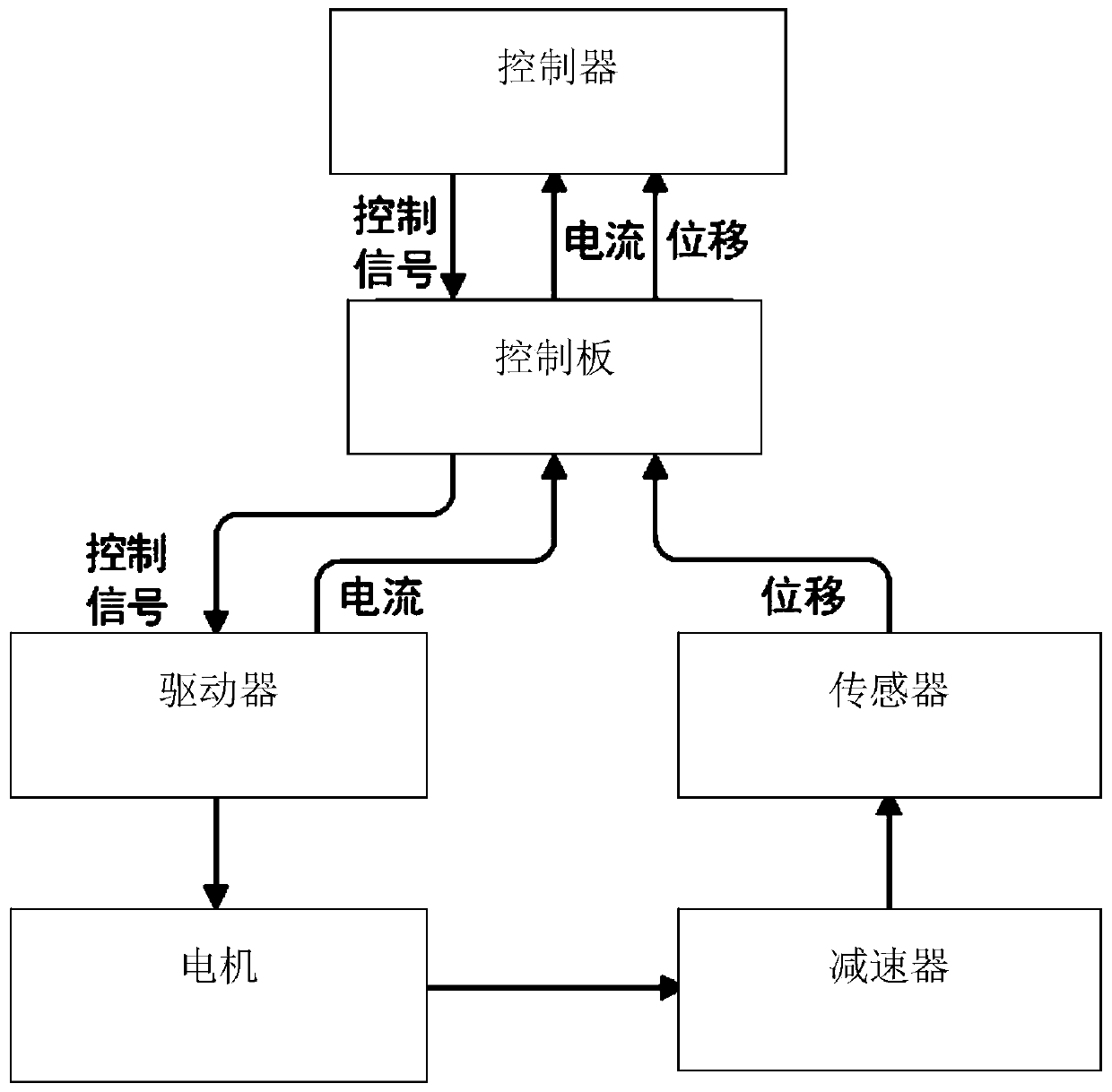
[0046] Such as figure 1 As shown, a motor closed-loop monitoring and control system includes a controller, a control board, a driver, a sensor, a motor and a reducer.

[0047] The controller is electrically connected with the control board, the controller monitors the current signal voltage fed back by the control board in real time, and the controller outputs the level signal for driving the control board.

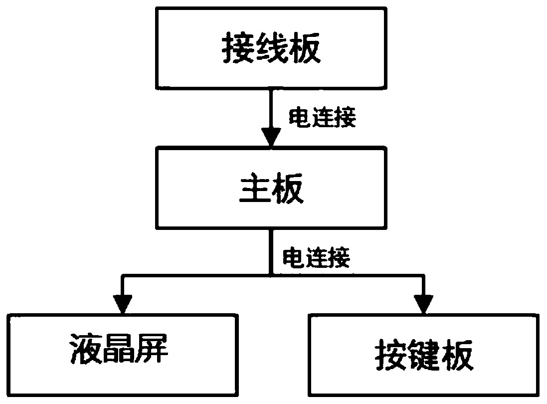
[0048] refer to figure 2 , the controller includes a wiring board, a main board, an LCD screen and a key board.

[0049] The wiring board is electrically connected to the main board, and the main board is electrically connected to the LCD screen and the key board respectively.

[0050] The wiring board is electrically connected with the control board.

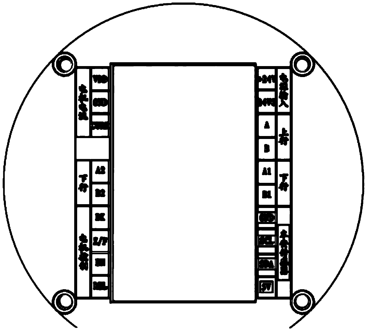
[0051] refer to image 3 , the wiring board includes a power input interface, an uplink communication inte...


PUM


Abstract

A motor closed-loop monitoring control system includes a controller, a control board, a driver, a motor, a reducer and a sensor. The controller is electrically connected with the control board, and the controller monitors a current signal voltage fed back by the control board in real time and outputs a level signal for driving the control board. The control board is electrically connected with thedriver, and the control board outputs an isolated level signal to control the driver. The driver is electrically connected with the motor, and the driver outputs a motor driving sequence to drive themotor. The motor is mechanically connected with the reducer. The reducer is mechanically connected with the sensor, and the sensor tests and records angle information output by the reducer. The sensor is electrically connected with the control board to output the angle value of the motor. The control board is electrically connected with the controller, and the control board outputs angle information to the controller through communication. The whole system adopts closed-loop control, so as to realize the lifting control and measurement of an oil pumping pipe of an oil-water pumping and draining device and ensure the smooth progress of the oil pumping work.

Description

technical field [0001] The invention belongs to the technical field of oilfield equipment, and relates to a motor control system of pumping and drainage equipment, in particular to a motor closed-loop monitoring control system and a control method. Background technique [0002] At present, the drainage and pumping of liquid storage tanks in oilfield gas gathering stations is still in the stage of manual operation. [0003] When pumping water, the monitoring personnel will open the valve remotely, and the personnel outside the station will lower the pipeline of the suction port to the bottom of the liquid storage tank based on experience. When pulling oil, the work area arranges guardians to go to the station, and the pulling personnel insert the hose on the car into the tank. According to experience, the hose head is parked in the oil layer. When cloudy, pull out the hose and stop working. [0004] However, the above-mentioned traditional methods all require on-site superv...

Claims


Application Information

Patent Timeline
Patent Type & Authority Applications(China)
IPC IPC(8): H02P6/17H02P6/06H02H7/085
CPCH02H7/0853H02P6/06H02P6/17
Inventor 王士兴杨朋王西平王士晨樊军鹏官军昌
Owner XIAN ANCN INTELLIGENT INSTR
Why Eureka
Try Eureka