Efficient waste heat power generation system

A high-efficiency waste heat power generation technology, which is applied in the directions of preheating, steam generation, feed water heater, etc., can solve the problem of no waste heat recovery and utilization method, and achieve the problem of serious dust accumulation in the flue, high stability and reliability, and reduced Effect of exhaust gas temperature

Inactive Publication Date: 2019-10-18
大航控股集团节能环保科技股份有限公司
View PDF5 Cites 0 Cited by
  • Summary
  • Abstract
  • Description
  • Claims
  • Application Information

AI Technical Summary

Problems solved by technology

How to effectively recover and utilize the waste heat of flue gas is of great significance. In the existing technology, there is a scheme of using the technology of "waste heat boiler + steam turbine" to recover and utilize the waste heat of flue gas. However, this kind of scheme is to recover the waste heat of high-temperature flue gas For the transformation of power generation technology, there is still no effective waste heat recovery and utilization method for flue gas with a flue gas temperature lower than 300C, or with a small amount of flue gas and less waste heat

Method used


Image

  • Efficient waste heat power generation system

Examples


Embodiment 1

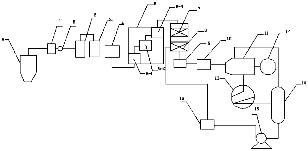
[0017] This embodiment provides a high-efficiency waste heat power generation system with a structure such as figure 1 Shown: including combustion system, tail body treatment device, power generation system and cooling system, combustion system includes preheater 1, primary combustion furnace 2, secondary combustion furnace 3 and heat exchange furnace 4, preheater 1 air inlet Connect the gas outlet of the boiler 5, the gas outlet of the preheater 1 is connected to the air inlet of the first-stage combustion furnace 2, and an induced draft fan 6 is arranged between the air outlet of the preheater 1 and the air inlet of the first-stage combustion furnace 2. The gas outlet of the primary combustion furnace 2 is connected to the air inlet of the secondary combustion furnace 3, the gas outlet of the secondary combustion furnace 3 is connected to the air inlet of the heat exchange furnace 4, the gas outlet of the heat exchange furnace 4 is connected to the air inlet of the tail gas t...


PUM


Abstract

The invention discloses an efficient waste heat power generation system which comprises a combustion system, a tail gas treatment device, a power generation system and a cooling system. The combustionsystem comprises a preheater, a first-stage combustion furnace, a second-stage combustion furnace and a heat exchange furnace. A gas inlet of the preheater is connected with a gas outlet of a boiler.A gas outlet of the preheater is connected with a gas inlet of the first-stage combustion furnace. A gas outlet of the first-stage combustion furnace is connected with a gas inlet of the second-stagecombustion furnace. A gas outlet of the second-stage combustion furnace is connected with a gas inlet of the heat exchange furnace. A gas outlet of the heat exchange furnace is connected with a gas inlet of the tail gas treatment device. The power generation system comprises an economizer, a steam pocket, an evaporator, a superheater, a steam turbine and an expansion generator connected with thesteam turbine. A gas inlet of the economizer is connected with a gas outlet of the tail gas treatment device. A gas outlet of the economizer is connected with a gas inlet of the steam pocket. A gas outlet of the steam pocket is connected with a gas inlet of the evaporator. A gas outlet of the evaporator is connected with a gas inlet of the superheater. A gas outlet of the superheater is connectedwith a gas inlet of the steam turbine. A gas outlet of the steam turbine is connected with the cooling system.

Description

technical field [0001] The invention relates to a high-efficiency waste heat power generation system. Background technique [0002] Flue gas waste heat resource loss is the most important waste heat resource loss, accounting for 60% to 70% of boiler waste heat resource loss. How to effectively recover and utilize the waste heat of flue gas is of great significance. In the existing technology, there is a scheme of using the technology of "waste heat boiler + steam turbine" to recover and utilize the waste heat of flue gas. However, this kind of scheme is to recover the waste heat of high-temperature flue gas For the transformation of power generation technology, there is still no effective waste heat recovery and utilization method for flue gas with a flue gas temperature lower than 300C, or with a small amount of flue gas and less waste heat. Contents of the invention [0003] The technical problem to be solved by the present invention is to provide a high-efficiency wast...

Claims


Application Information

Patent Timeline
Patent Type & Authority Applications(China)
IPC IPC(8): F22B31/00F22B33/18F22D1/00F22D1/50F23J15/02F01K11/02F01D15/10
CPCF22B31/00F22B33/18F22D1/00F22D1/50F23J15/02F01K11/02F01D15/10F23J2215/10F23J2215/101F23J2215/20
Inventor 施建中唐小兵张明锦
Owner 大航控股集团节能环保科技股份有限公司
Why Eureka
Try Eureka