Dual-cone rotary vacuum dryer

A vacuum dryer, rotary technology, applied in non-progressive dryers, dryers, drying solid materials, etc., can solve the problems of inconsistent pressure in the interlayer, poor temperature uniformity, and slow material acceptance of heat energy, etc., to achieve The maintenance and operation of equipment is simple, the drying time is shortened, and the heat conduction is fast.

Pending Publication Date: 2019-10-18
NANJING SHENPENG MACHINERY EQUIP
View PDF0 Cites 3 Cited by
  • Summary
  • Abstract
  • Description
  • Claims
  • Application Information

AI Technical Summary

Problems solved by technology

[0003] The technical problem to be solved by the present invention is: the traditional dryer enters oil at one point through the interlayer, resulting in inconsistent pressure in the interlayer, slow heat conduction in the inner cone, slow heat acceptance by the material, and poor temperature uniformity; at the same time, the traditional double cone Rotary vacuum dryer adopts a rated speed. It is not clear whether the material fluid in the cone is sliding or turning. If it is sliding, it will directly affect the drying, and the speed will be difficult to change, resulting in poor drying effect and low efficiency.

Method used


Image

  • Dual-cone rotary vacuum dryer
  • Dual-cone rotary vacuum dryer

Examples


Embodiment 1

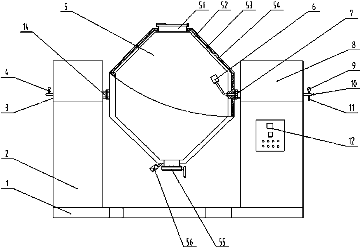
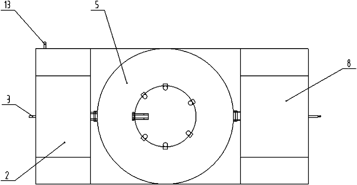
[0017] This embodiment provides a double-cone rotary vacuum dryer with a structure such as figure 1 and figure 2 As shown, it includes: left bracket 2, right bracket 8 and barrel 5, left bracket 2 and right bracket 8 are installed on the two ends of base 1 respectively, first rotating shaft 14 is installed on the top of left bracket 2, first rotating shaft 14 The outer end is provided with a steam inlet 3, a pressure gauge 4 is installed on the outside of the steam inlet 3, a condensed water outlet 13 is arranged on the side below the left bracket 2, a second rotating shaft 7 is installed above the right bracket 8, and the barrel 5 is respectively connected to the first The rotating shaft 14 and the second rotating shaft 7 are connected with bearings. The barrel 5 is a biconical structure with two pointed ends facing away from each other. The barrel 5 includes an outer shell 54 and an inner shell 52, and an interlayer 53 is arranged between the outer shell 54 and the inner sh...


PUM


Abstract

The invention discloses a dual-cone rotary vacuum dryer. The dryer comprises a left support, a right support and a charging barrel. The left support and the right support are arranged on the two endsof a base, a first rotating shaft is arranged above the left support, a steam inlet is formed in the end of the outer side of the first rotating shaft, a condensate outlet is formed in the side face of the lower portion of the left support, a second rotating shaft is arranged above the right support, the charging barrel is in fit bearing connection with the first rotating shaft and the second rotating shaft, the charging barrel is of a dual-cone structure with two tip ends which are reverse and face outwards, the charging barrel comprises an outer shell and an inner shell, an interlayer is arranged between the outer shell and the inner shell, a feeding opening is formed in the upper end of the charging barrel, a discharging opening is formed in the lower end of the charging barrel, a motorand a speed reducer are arranged in the right support, the speed reducer is connected with the second rotating shaft through a belt and belt wheels, a vacuum connector is formed in the end of the outer side of the second rotating shaft, a control cabinet is arranged in the right support, and an anti-explosion control box is arranged on the outer side of the control cabinet. The effects of being good in drying effect and high in efficiency are achieved.

Description

technical field [0001] The invention belongs to the field of chemical machinery, in particular to a double-cone rotary vacuum dryer. Background technique [0002] The double-cone rotary vacuum dryer is a double-cone rotary tank. In the vacuum state, steam or hot water is passed into the jacket for heating. The heat contacts the wet material through the inner wall of the tank, and the wet material evaporates after absorbing heat. The water vapor is sucked away through the vacuum exhaust pipe by the vacuum pump. The inside of the tank is in a vacuum state, and the rotation of the tank makes the material continuously turn up and down, so as to achieve the purpose of uniform drying. Double cone rotary vacuum dryer is a drying equipment integrating mixing and vacuum drying. The process of vacuum drying is to place the material to be dried in a sealed cylinder, and heat the material to be dried while vacuuming with a vacuum system, so that the moisture inside the material diffus...

Claims


Application Information

Patent Timeline
Patent Type & Authority Applications(China)
IPC IPC(8): F26B5/04F26B11/04F26B25/16
CPCF26B5/04F26B11/04F26B25/16
Inventor 陈从林
Owner NANJING SHENPENG MACHINERY EQUIP
Why Eureka
Try Eureka