A vacuum steelmaking furnace

A steelmaking furnace and vacuum technology, applied in the field of steelmaking furnaces, can solve the problems of increasing raw material and energy consumption, insufficient contact, and prolonging smelting time, so as to achieve sufficient and thorough reaction of raw materials, reduce heat loss, and avoid artificial dredging effect

Active Publication Date: 2020-12-04
山东天智信息科技有限公司
View PDF5 Cites 1 Cited by
  • Summary
  • Abstract
  • Description
  • Claims
  • Application Information

AI Technical Summary

Problems solved by technology

[0003] When the existing steelmaking furnace makes steel, the steelmaking furnace generally rotates horizontally, so that during oxygen blowing and bottom blowing, the space for interaction between molten steel and reactants in the furnace is too small, resulting in insufficient contact and prolonging the smelting time. It also affects the quality of the steel, and the temperature difference between the inside and outside of the furnace is extremely large, resulting in low smelting efficiency. During the smelting process, it is necessary to replenish lime, carbon powder and other raw materials in time. The feeding pipe and the discharge port of the silo are often blocked in the process, and it is necessary to stop the production and manually dredge, which is time-consuming and laborious, and the mixing is not sufficient, which affects the quality of the product. Moreover, the vacuuming speed of the existing steelmaking furnace is relatively slow, which affects the quality of the steelmaking process. Efficiency, increased consumption of raw materials and energy

Method used


Image

  • A vacuum steelmaking furnace
  • A vacuum steelmaking furnace
  • A vacuum steelmaking furnace

Examples


Embodiment Construction

[0028] In order to make the purpose, features and advantages of the present invention more obvious and understandable, the technical solutions in the embodiments of the present invention will be clearly and completely described below with reference to the accompanying drawings in the embodiments of the present invention. Obviously, the following The described embodiments are only some, but not all, embodiments of the present invention. Based on the embodiments of the present invention, all other embodiments obtained by those of ordinary skill in the art without creative efforts shall fall within the protection scope of the present invention.

[0029] The technical solutions of the present invention are further described below with reference to the accompanying drawings and through specific embodiments.

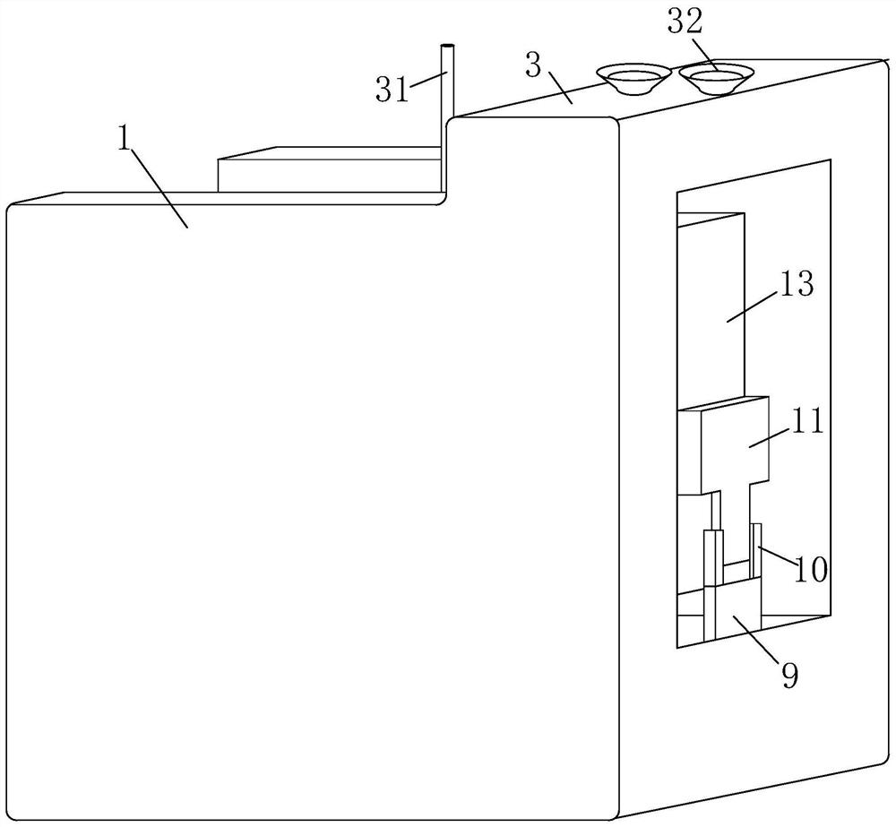
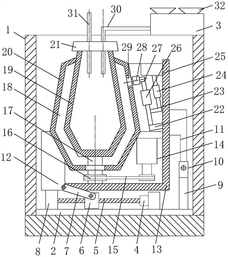
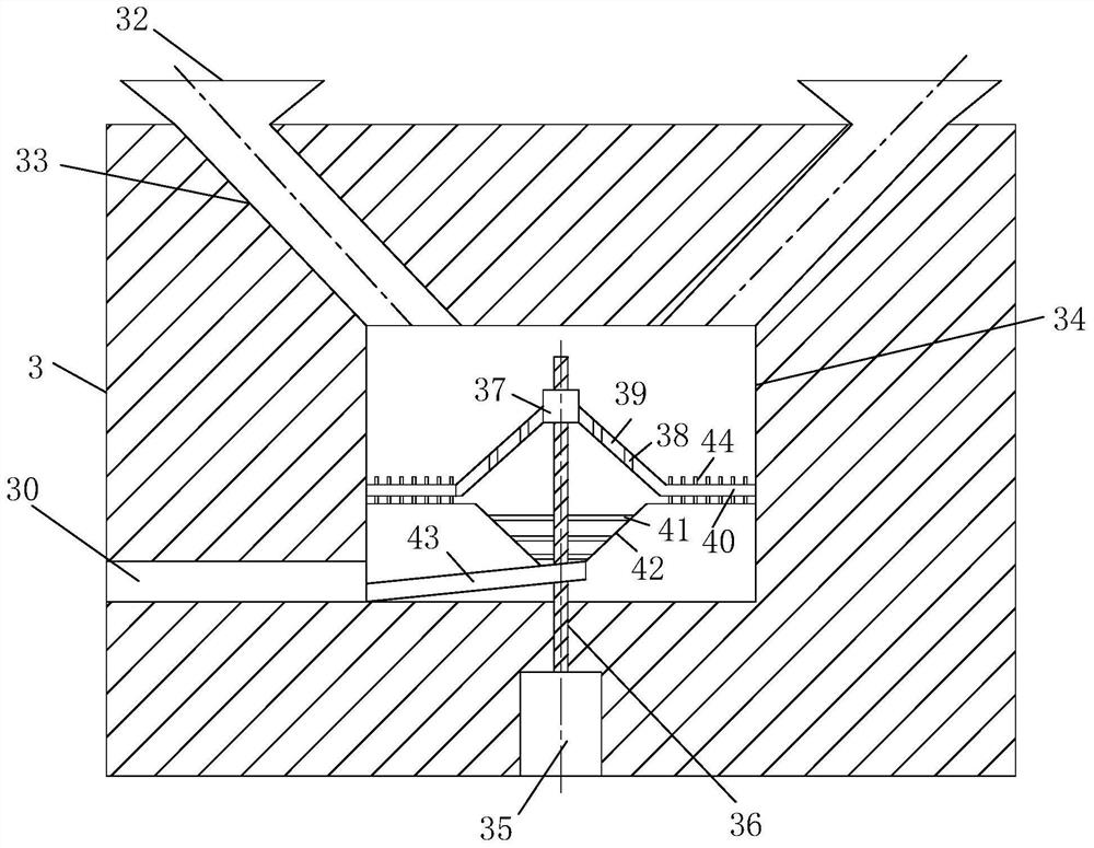
[0030] see Figure 1-5 As shown, a vacuum steelmaking furnace includes a shell 1 and a regulating device, a vacuum device and a mixing device; the regulating device comprises...


PUM


Abstract

The invention belongs to the technical field of steel smelting furnaces, and particularly relates to a vacuum steel smelting furnace. A shell, a bottom plate, a feeding box, a first motor, a lead screw, a movable block, a connecting rod, a limiting plate, a fixing plate, a movable plate, a first connecting block, a second connecting block, a fixing frame, a second motor, a belt, a belt wheel, a transmission shaft, a vacuum cavity, an inner furnace, an outer furnace, a seal furnace crown, a vacuum pump, a connecting pipe, a first air cylinder valve, a storage tank, an air blower, a communication pipe, a second air cylinder valve, an air pipe, a feeding pipe, an oxygen inlet pipe, a feeding hopper, a discharging pipe, a stirring cavity, a third motor, a stirring shaft, a casing pipe, a conical barrel, screen holes, a grinding barrel, a stirring bar, a mixing hopper, a material outlet pipe and grinding teeth are included. Through matched communication of the storage tank, the first air cylinder valve, the second air cylinder valve, the connecting pipe and the communication pipe, vacuum pumping is only conducted on the vacuum cavity through the vacuum pump and the air blower, accordingly, rapid vacuum pumping of the vacuum cavity is achieved, the steel smelting efficiency is improved, and heat losses are reduced.

Description

technical field [0001] The invention belongs to the technical field of steelmaking furnaces, in particular to a vacuum steelmaking furnace. Background technique [0002] Steelmaking refers to controlling the carbon content (generally less than 2%), eliminating harmful elements such as P, S, O, N, retaining or increasing beneficial elements such as Si, Mn, Ni, Cr, and adjusting the ratio between the elements to obtain the best To improve the performance, put the pig iron for steelmaking into the steelmaking furnace and smelt it according to a certain process, that is, to obtain steel. Steel products include ingots, continuous casting billets, and direct casting into various steel castings. Generally speaking, steel generally refers to steel rolled into various steels. Steel belongs to ferrous metals, but steel is not completely equal to ferrous metals. [0003] When making steel in the existing steelmaking furnace, the steelmaking furnace generally rotates horizontally. In t...

Claims


Application Information

Patent Timeline
Patent Type & Authority Patents(China)
IPC IPC(8): F27B14/04F27B14/08F27B14/16F27D3/00C21C7/10
CPCC21C7/10F27B14/04F27B14/08F27B14/0806F27B2014/045F27D3/0026F27M2001/02F27M2003/13
Inventor 程郎郭义强王玉芹
Owner 山东天智信息科技有限公司
Why Eureka
Try Eureka