
Method for distributing working voltage proportion of voltage dependent resistor and discharge tube series circuit

A varistor and working voltage technology, applied in circuit devices, emergency protection circuit devices for limiting overcurrent/overvoltage, emergency protection circuit devices, etc., can solve poor contact of zero line and withstand abnormal fluctuations in grid voltage Weakness, increased discharge tube thickness and other issues, to achieve the effect of reducing procurement costs, improving protection level, and reducing thickness

Inactive Publication Date: 2019-10-18
CHENGDU TIEDA ELECTRONICS CORP
View PDF5 Cites 0 Cited by
  • Summary
  • Abstract
  • Description
  • Claims
  • Application Information

AI Technical Summary

Problems solved by technology

[0003] Due to the extreme imbalance of the working voltage distribution, some disadvantages are brought about. First, the DC breakdown voltage value of the discharge tube needs to be selected higher, which increases the thickness of the discharge tube and increases the price; the second is to withstand abnormal fluctuations in the grid voltage. The capacity of the discharge tube is weak, unless the DC breakdown voltage value of the discharge tube is further greatly increased; the third is that after the DC breakdown voltage value of the discharge tube is increased, the corresponding impulse discharge voltage value will also increase, and the surge wave head will enter the subsequent stage The amplitude of the protected circuit will also be higher, which affects the protection effect
In addition, when the series circuit is used as a part of some more complex combination circuits, it will not achieve the best effect due to the unsatisfactory working voltage distribution.
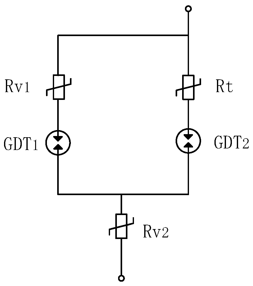
[0004] Chinese invention patent number 201811040267.8 discloses a surge protection circuit, such as figure 2 As shown, in the actual application of this circuit, since the inherent capacitance of the discharge tubes GDT1 and GDT2 is very small, under the normal state without surge impact, the grid operating voltage at both ends of the circuit is almost all added to the two discharge tubes, while the GDT2's The DC breakdown voltage value cannot be selected too high, which will cause the circuit's ability to withstand abnormal fluctuations in grid voltage is not high
For example, in the usual 220V power frequency power grid, one of the more common grid faults is poor contact or open circuit of the zero line, causing the line voltage to rise to close to 380V for a short time. At this time, GDT2 will be turned on and the thermal protection function will be activated in advance. action, allowing the circuit to exit the grid without damage, causing waste
In a more special case, when Rv2 has deteriorated to a certain extent, Rv2 may also be broken down when encountering such a grid fault. At this time, the abnormal overvoltage of the grid up to 380 volts will be directly added to both ends of GDT1 , if its DC breakdown voltage value is lower than 550 volts, it will also conduct, causing Rv1 to break down and short circuit, so that the circuit's open circuit exits and the function of safety failure is lost, causing a short circuit fault in the grid line

Method used


Image

  • Method for distributing working voltage proportion of voltage dependent resistor and discharge tube series circuit
  • Method for distributing working voltage proportion of voltage dependent resistor and discharge tube series circuit
  • Method for distributing working voltage proportion of voltage dependent resistor and discharge tube series circuit

Examples


Embodiment 1

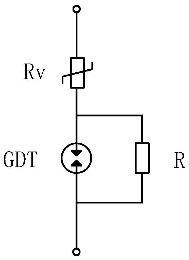
[0025] The invention proposes a technical solution, that is, in a 50 Hz low-voltage AC transmission line with a voltage below 600 volts, a surge protector connected in series with a piezoresistor and a discharge tube is used as a secondary or tertiary surge protection. After the resistor and the discharge tube are connected in series, a resistor element is connected in parallel at both ends of the discharge tube to adjust the impedance, so as to achieve the purpose of redistributing the working voltage load ratio. The specific circuit is as follows: figure 1 As shown, by designing the resistance value of the resistor, the operating voltage load at both ends of the discharge tube can be arbitrarily selected from close to the voltage at both ends of the series circuit (represented by Uc) to close to zero. When the resistance value of the resistor is much smaller than the inherent capacitive reactance of the varistor, the working voltage Uc can be approximately regarded as being ...

Embodiment 2

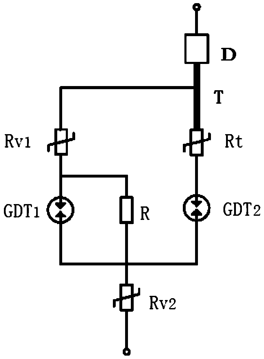
[0043] Another embodiment of the present invention is image 3 shown. A series-parallel combined circuit that distributes the working voltage ratio of the series circuit of the piezoresistor and the discharge tube. The circuit is designed for a high-safety surge suppression chip dedicated to surge protectors in power frequency AC transmission lines below 600 volts. This circuit has the important function of safely withdrawing from the power grid after failure, and avoids sudden accidents such as power outages in the power grid caused by the failure of the surge protector due to unexpected reasons such as extremely large lightning strikes. The circuit includes a first piezoresistor Rv1, a second piezoresistor Rv2, a first discharge tube GDT1, a second discharge tube GDT2, a positive temperature coefficient thermistor Rt, a resistor R and a terminal T, the first discharge tube GDT1 is connected in parallel with resistor R, and then forms a series-parallel circuit (ie, the first...


PUM


Abstract

The invention discloses a method for distributing the working voltage proportion of a voltage dependent resistor and discharge tube series circuit in the surge protection field. According to the method of the invention, after a voltage dependent resistor and a discharge tube are connected in series into a power-frequency power grid, a resistor is connected in parallel at the discharge tube, so that the load proportions of the working voltage of the power grid on various elements can be conveniently adjusted. According to the method disclosed by the invention, the discharge tube with a low direct-current breakdown voltage value can be selected, the amplitude of wave heads which are shifted before the discharge tube is switched on during the generation of surge is effectively reduced, a protection level is improved, and more margin for the tolerance of the abnormal fluctuation of the voltage of the power grid is realized.

Description

technical field [0001] The invention relates to the field of surge protection, in particular to a method for distributing the working voltage ratio of a series circuit of a piezoresistor and a discharge tube. Background technique [0002] It is a common method in surge protection technology to connect the varistor and the discharge tube in series to the power frequency grid. In the state of no surge, since the discharge tube is disconnected, there is almost no resistive current passing through the series circuit, only the inherent capacitance of the two components connected in series causes a weak capacitive current to pass through, and the capacitive current is multiplied by The respective capacitive reactance can be used to obtain the partial voltage of the grid operating voltage on each component, and the sum of the partial voltages of the two components is equal to the voltage at both ends of the series circuit (represented by Uc). The inherent capacitance value of the ...

Claims


Application Information

Patent Timeline
Patent Type & Authority Applications(China)
IPC IPC(8): H02H9/04H02H9/06H02H9/00H02H9/02
CPCH02H9/04H02H9/06H02H9/005H02H9/02
Inventor 石小龙张治成叶磊詹俊鹄章俊
Owner CHENGDU TIEDA ELECTRONICS CORP
Learn More