
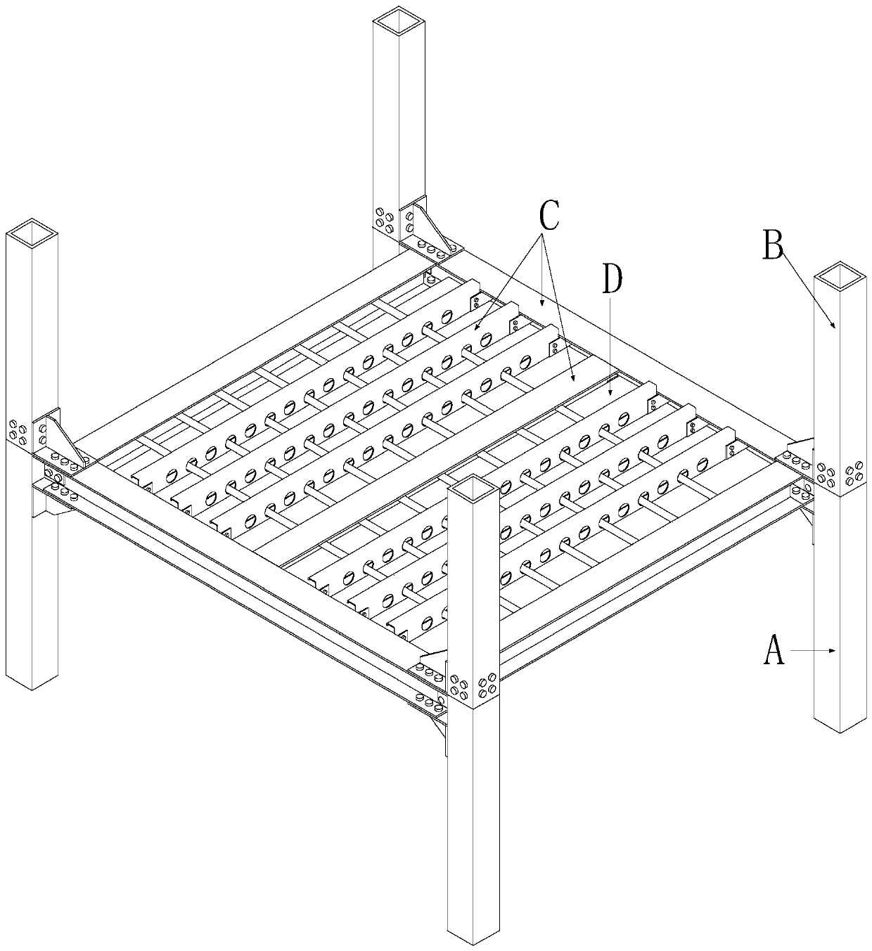
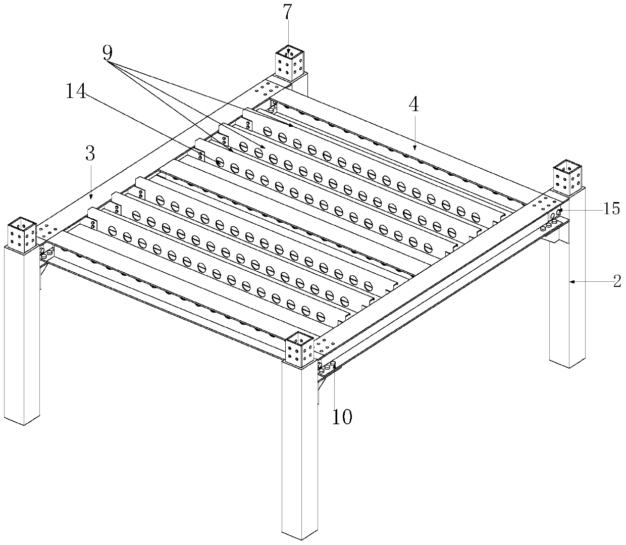
Assembled building system based on inner insertion plate and clamping plate connecting beam column nodes

A prefabricated and inter-insert board technology, applied in the direction of architecture, building components, building structures, etc., can solve the problems of low professional level of construction personnel, difficulty in detection of construction quality on site, and difficulty in guaranteeing construction quality, so as to achieve easy quality assurance , fast assembly speed, and the effect of improving the net height

Active Publication Date: 2019-10-22
BEIJING UNIV OF TECH
View PDF8 Cites 2 Cited by
  • Summary
  • Abstract
  • Description
  • Claims
  • Application Information

AI Technical Summary

Problems solved by technology

[0002] Traditional building construction methods include formwork, on-site tying of steel bars, and pouring of concrete. There are many construction steps and it is not conducive to the comprehensive deployment of personnel. The professional level of construction personnel is low, and the quality of on-site construction is difficult to detect and difficult to guarantee.
At the same time, in the construction process, a large amount of disposable consumables are required, resulting in a great waste of materials; moreover, the construction period is long and the cost of personnel wages is large

Method used


Image

  • Assembled building system based on inner insertion plate and clamping plate connecting beam column nodes
  • Assembled building system based on inner insertion plate and clamping plate connecting beam column nodes
  • Assembled building system based on inner insertion plate and clamping plate connecting beam column nodes

Examples


Embodiment Construction

[0047] In order to make the objectives, technical solutions, and advantages of the embodiments of the present invention clearer, the technical solutions in the embodiments of the present invention will be described clearly and completely in conjunction with the accompanying drawings in the embodiments of the present invention. Obviously, the described embodiments It is a part of the embodiments of the present invention, but not all the embodiments. Based on the embodiments of the present invention, all other embodiments obtained by those of ordinary skill in the art without creative work shall fall within the protection scope of the present invention.

[0048] In the description of the present invention, it should be noted that the terms "center", "upper", "lower", "left", "right", "vertical", "horizontal", "inner", "outer", etc. The indicated orientation or positional relationship is based on the orientation or positional relationship shown in the drawings, which is only for the...


PUM


Abstract

The invention discloses an assembled building system based on inner insertion plate and clamping plate connecting beam column nodes. A lower column module comprises lower columns; all the lower columns are provided with first support plates, outer extension plates and inner insertion plates; an upper column module comprises upper columns; all the upper columns are provided with second support plates; the upper columns are correspondingly inserted in the inner insertion plates of the lower columns, and are connected through bolts; a beam module comprises a main beam and a secondary beam; wire passing holes are reserved on web plates of the main beam and the secondary beam; and the connection of all the modules is realized through bolts among the main beam web plate, the outer extension plates and clamping plates, between a main beam lower flange and the first support plates and between a main beam upper flange and the second support plates. Beam columns can be assembled in scene only byadopting bolts, so that the assembly speed is high, and the construction period is shortened. Ribbed support plates achieve a positioning effect on the beams to bear part of the bending moment. The upper and lower columns are conveniently installed by the inner insertion plates to reduce the lifting difficulty. The ribbed support plates and the clamping plates are provided to realize outer shifting of plastic hinges. Pipelines are separated from a main body structure, so that the maintenance is convenient, and the clearance is improved.

Description

Technical field [0001] The invention belongs to the technical field of structural engineering, and relates to a prefabricated building system with pipeline separation, in particular to a prefabricated building system based on interposer plates and splints connecting beam-column nodes. Background technique [0002] Traditional building construction methods include formwork, on-site tying of steel bars, and concrete pouring. There are many construction steps and are not conducive to the comprehensive deployment of personnel. The level of professionalism of construction personnel is low. The quality of on-site construction is difficult to detect and the quality of construction is difficult to guarantee. At the same time, in the construction process, a large amount of disposable consumables are required, which causes a great waste of materials; in addition, the construction period is long and the personnel wages are expensive. The above problems have contributed to the development of...

Claims


Application Information

Patent Timeline
IPC IPC(8): E04B1/24E04B1/58E04B5/48
CPCE04B1/24E04B1/2403E04B5/48E04B2001/2415E04B2001/2418E04B2001/2454E04B2001/2484
Inventor 刘学春王玥
Owner BEIJING UNIV OF TECH
Learn More