An assembled energy-dissipating node connected to a suspended steel column and its installation method

A prefabricated and node-based technology, applied in protective buildings/shelters, building types, buildings, etc., can solve the problems of reducing the seismic performance of sub-floors, the impact of sub-floor safety performance, failure, etc., to achieve strong recoverability, Improvement of the effect of evacuating seismic energy and the effect of stable performance

Active Publication Date: 2022-05-17
HEFEI UNIV OF TECH +1
View PDF0 Cites 0 Cited by
  • Summary
  • Abstract
  • Description
  • Claims
  • Application Information

AI Technical Summary

Problems solved by technology

Under the action of wind load or earthquake load, there will be a relatively large interstory displacement difference between the infill sub-floor and the main structure, and the key nodes of the suspended steel columns may fail, resulting in a reduction in the seismic performance of the sub-floor, making the sub-floor Safety performance is affected

Method used


Image

  • An assembled energy-dissipating node connected to a suspended steel column and its installation method
  • An assembled energy-dissipating node connected to a suspended steel column and its installation method
  • An assembled energy-dissipating node connected to a suspended steel column and its installation method

Examples


Embodiment 1

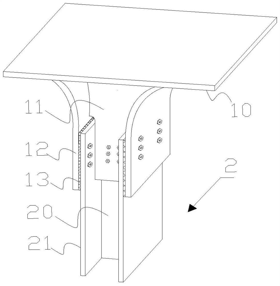
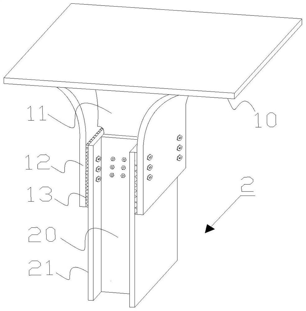
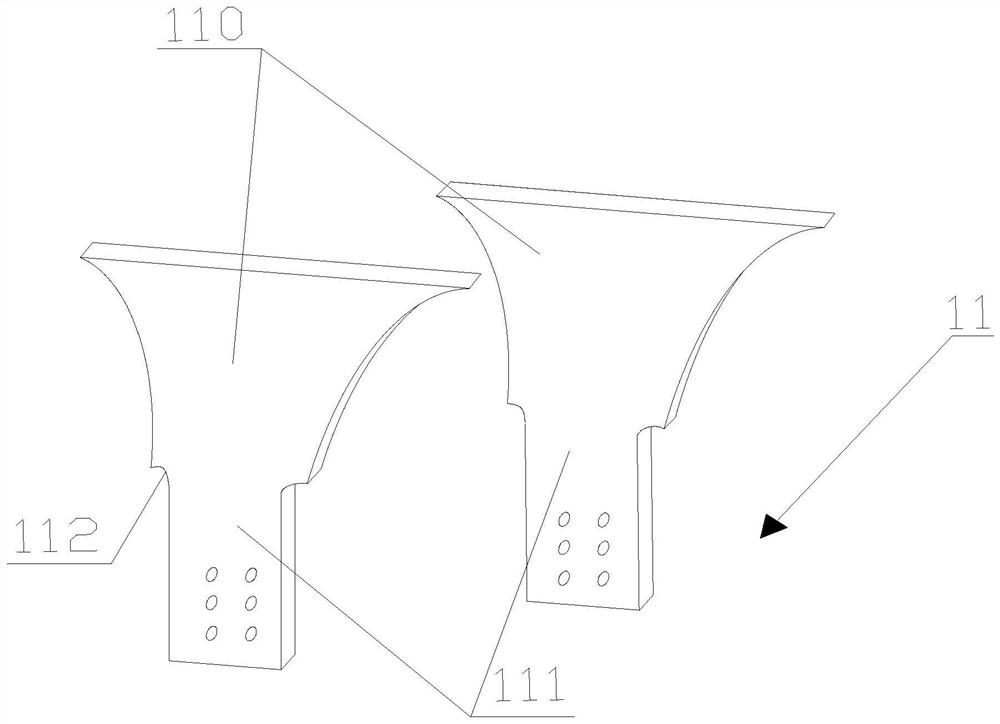
[0043] A fabricated energy-dissipating node connected to suspended steel columns, such as figure 1 with figure 2 The energy dissipation node includes an end plate 10, two energy dissipation node webs 11 arranged front and back, and two energy dissipation node flanges 12 arranged left and right, as image 3 As shown, each energy-dissipating node web 11 includes a web arc section 110 and a web straight section 111, as shown in Figure 4 As shown, each energy dissipation node flange 12 includes a flange arc segment 120 and a flange straight segment 121 . The end plate 10 is welded to the top of the web arc section 110 and the top of the flange arc section 120, and the flange is the wing plate. The energy dissipation node flanges 12 are arranged opposite to each other, the energy dissipation node webs 11 are arranged opposite to each other, and the energy dissipation node webs 11 are located between the opposite energy dissipation node flanges 12 .

[0044] Both the flange arc...

Embodiment 2

[0050] On the basis of Example 1, such as Figure 8 As shown, the main structure of the whole floor is a giant frame, and the giant frame includes a frame column 5 and a horizontal member 3 fixed on the top of the frame column 5. A number of energy-dissipating nodes are suspended on the horizontal member 3, which bears the main gravity of the floor 4. Installing the energy-consuming node of the present invention on the megaframe comprises the following steps:

[0051] S1, two energy dissipation node webs 11 are welded opposite to each other on the end plate 10, and the two energy dissipation node webs 11 are parallel; the flange arc section 120 of the energy dissipation node flange 12 is attached to the web On the arc section 110, the flange 12 of the energy-dissipating node is welded to the end plate 10, and the prefabrication of the energy-dissipating node is completed at this time;

[0052] S2, fixing the elastic member 13 on the flange straight section 121;

[0053] S3,...


PUM


Abstract

The invention relates to the field of construction engineering, in particular to an assembled energy-dissipating node connected to a suspended steel column and an installation method thereof. The energy dissipation node includes end plates, energy dissipation node webs, and energy dissipation node flanges. The energy dissipation node flanges are arranged opposite to each other, and the energy dissipation node webs are arranged opposite to each other. At the top of both the node webs, the dissipating node webs are located between the opposing dissipating node flanges; the dissipating node webs and the dissipating node flanges are used to hold the suspended steel columns. When wind load or earthquake load occurs, energy-dissipating nodes can consume the energy generated by them, reduce the interstory displacement difference between the infill sub-floor suspended on the suspended steel column and the main structure, and improve the seismic performance of the sub-floor , so that the safety performance of the sub-floor is guaranteed.

Description

technical field [0001] The invention relates to the field of construction engineering, in particular to an assembled energy-dissipating node connected to a suspended steel column and an installation method thereof. Background technique [0002] With the continuous development of structural engineering technology, buildings are increasingly developing towards long-span and high-rise buildings. Compared with the traditional steel frame, the suspended structure system is a structural system that can provide greater space requirements. It has a unique architectural shape, superior structural performance, effectively reduces the amount of steel used in the building, and generates huge social and social benefits. Economic Value. [0003] In the suspended structure system, the load of the infill sub-floor is transferred to the top horizontal member of the giant frame column through the suspended steel column and energy-dissipating nodes, and further transmitted to the frame column...

Claims


Application Information

Patent Timeline
Patent Type & Authority Patents(China)
IPC IPC(8): E04B1/24E04B1/58E04B1/98E04H9/02
CPCE04B1/2403E04H9/024
Inventor 王静峰张坤李德章丁敬华郭磊
Owner HEFEI UNIV OF TECH
Why Eureka
Try Eureka