Processing method for blowing type soaking plate with capillary structure
A capillary structure and processing method technology, applied in the field of heat dissipation, can solve the problems of filler deformation, affecting the formation of capillary structure, breaking, etc., to achieve the effect of avoiding deformation and improving heat dissipation effect
- Summary
- Abstract
- Description
- Claims
- Application Information
AI Technical Summary
Problems solved by technology
Method used
Image
Examples
Embodiment 1
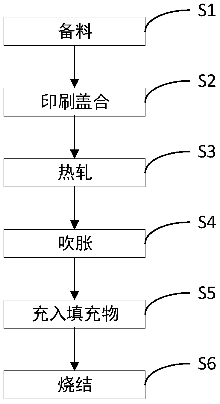
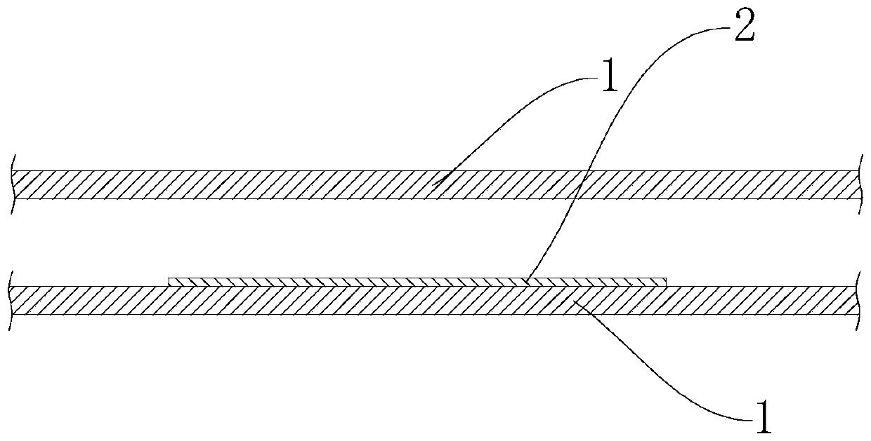
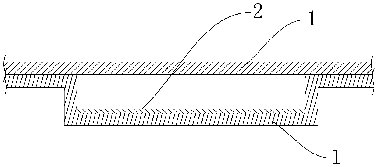
[0035] see Figure 1 to Figure 4 , Embodiment 1 of the present invention provides a method for processing an inflatable vapor chamber with a capillary structure, which specifically includes the following steps:
[0036] Step S1: prepare materials, prepare two substrates 1, in this embodiment, the two substrates 1 are aluminum plates, and the model of the aluminum plates is 3003.
[0037] Step S2: Printing and covering, cleaning and roughening one of the substrates 1, and printing anti-rolling agent 2 on the roughened surface of the substrate 1 according to the figure of the inflated cavity or flow path required by the process. The anti-rolling agent 2 is cured on the substrate 1 after being dried, and then another substrate 1 is covered on the substrate 1 on which the anti-rolling agent 2 is printed, so that the anti-rolling agent 2 is located between the two substrates 1 .
[0038] In this embodiment, the anti-rolling agent 2 is graphite emulsion or boron nitride emulsion. ...
Embodiment 2
[0057] see Figure 5 The difference between the processing method of an inflatable vapor chamber with a capillary structure provided in Embodiment 2 of the present invention and the processing method of an inflatable vapor chamber with a capillary structure in Embodiment 1 is that in this embodiment, A heat conduction plate 31 is provided on the outer surface of at least one of the two substrates 1 , and the heat conduction plate 31 and the substrate 1 connected thereto together constitute the copper-aluminum composite plate 3 . The thermal conductivity of the heat conducting plate 31 is higher than that of the substrate 1 . Understandably, the material of the heat conducting plate 31 may be copper or copper alloy. In this embodiment, the covering rate of the heat conduction plate 31 is 3 to 30%. It should be noted that the cladding ratio refers to the ratio of the thickness of the heat conducting plate 31 to the total thickness of the composite plate. When processing, it i...
Embodiment 3
[0063] The difference between the processing method of the inflatable vapor chamber with the capillary structure provided in the third embodiment of the present invention and the processing method of the inflatable vapor chamber with the capillary structure in the second embodiment is that in this embodiment, the The two substrates 1 and the heat conduction plate 31 are hot-rolled at the same time. After one of the substrates 1 is cleaned and roughened, the anti-rolling agent 2 is printed on the roughened surface of the substrate 1 and riveted with the other substrate 1 and the heat conduction plate 31 to conduct heat. Plate 31 is on the outside. During processing, it is only necessary to provide the heat conduction plate 31 to be rolled simultaneously with the two base plates 1 and to be inflated between the two base plates 1 .
[0064] In this embodiment, before hot rolling, the thickness of one substrate 1 is 1.5-3.0 mm, the thickness of the other substrate 1 is 1.0-2.0 mm,...
PUM
| Property | Measurement | Unit |
|---|---|---|
| Particle size | aaaaa | aaaaa |
| Thickness | aaaaa | aaaaa |
| Thickness | aaaaa | aaaaa |
Abstract
Description
Claims
Application Information
 - R&D
- Intellectual Property
- Life Sciences
- Materials
- Tech Scout
- Unparalleled Data Quality
- Higher Quality Content
- 60% Fewer Hallucinations
Browse by: Latest US Patents, China's latest patents, Technical Efficacy Thesaurus, Application Domain, Technology Topic, Popular Technical Reports.
© 2025 PatSnap. All rights reserved.Legal|Privacy policy|Modern Slavery Act Transparency Statement|Sitemap|About US| Contact US: help@patsnap.com


