Visual inspection system for large precision shaft part
A visual inspection and precision axis technology, applied in the field of mechanical parts inspection, can solve problems such as fatigue of inspection personnel, high measurement cost, and poor anti-interference ability, and achieve real-time acquisition of measurement results, strong environmental adaptability, and fast collection and processing Effect
- Summary
- Abstract
- Description
- Claims
- Application Information
AI Technical Summary
Problems solved by technology
Method used
Image

Examples
Embodiment 1
[0042] A visual inspection system for large precision shaft parts, characterized in that it includes: a control module and a measurement module.
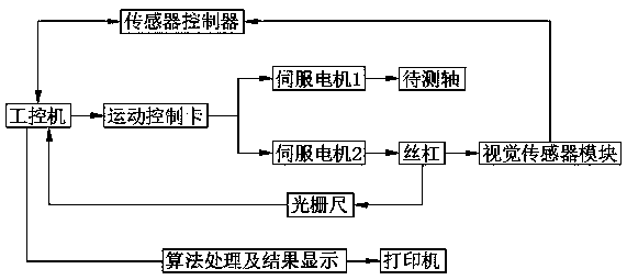
[0043] according to figure 1 , the control module includes: an industrial computer for sending instructions and receiving and processing data information; a motion control card for receiving instructions sent by the industrial computer and controlling the operation of the servo motor; for printing out information such as detection data and results , a printer for later archiving or other purposes; a sensor controller for controlling the visual sensor module for data collection, and an electronic control system for the circuit connection of the entire system, as well as operation buttons and indicator lights.
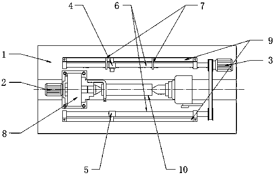
[0044] according to figure 2 , the measurement module includes: a visual sensor module for data acquisition of the axis 10 to be measured; a grating ruler 9 for transferring the distance moved by the visual sensor module to ...
Embodiment 2
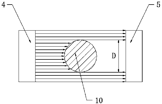
[0065] Such as Figure 4 As shown, the structural principle of this embodiment is similar to that of Embodiment 1, and the difference with Embodiment 1 is that the transmitter 4 and receiver 5 in the visual inspection module are composed of two sets of small transmitters: transmitter one 41 , transmitter two 42 and two sets of small receivers: receiver one 51 and receiver two 52, which are respectively located on both sides of the axis to be measured 10 and distributed up and down, wherein the distance L between the two sets of small CCD sensors is passed The standard shaft is calibrated. The diameter D of the shaft 10 to be measured in this embodiment can be calculated by the formula D=d1+d2+L, where d1 and d2 are measured by the visual inspection module.
PUM
 Abstract
Description
Claims
Application Information
 - Generate Ideas
- Intellectual Property
- Life Sciences
- Materials
- Tech Scout
- Unparalleled Data Quality
- Higher Quality Content
- 60% Fewer Hallucinations
Browse by: Latest US Patents, China's latest patents, Technical Efficacy Thesaurus, Application Domain, Technology Topic, Popular Technical Reports.
© 2025 PatSnap. All rights reserved.Legal|Privacy policy|Modern Slavery Act Transparency Statement|Sitemap|About US| Contact US: help@patsnap.com