Creep fatigue test system

A technology of creep fatigue test and sodium storage, which is applied in the field of creep fatigue test system, can solve the problems that corrosion is difficult to form, and it is impossible to simulate the stretching and damage of parts, and achieve the effect of simple structure

Active Publication Date: 2019-10-22
WUHAN INSTITUTE OF TECHNOLOGY +1
View PDF4 Cites 1 Cited by
  • Summary
  • Abstract
  • Description
  • Claims
  • Application Information

AI Technical Summary

Problems solved by technology

[0002] Existing creep fatigue testing machines are mainly used for tension, compression durability, creep, relaxation tests and low cycle fatigue and creep fatigue tests of metal and non-metallic materials, but in the actual industrial production environment, the parts are in the surrounding Under the action of medium (the most common are gases and liquids), due to a period of chemical changes, electrochemical changes or physical dissolution, damage will occur and corrosion will occur. When performing fatigue tests, due to the time consumed by actual experiments compared with manufacturing The time required for parts to corrode is much shorter, and corrosion is difficult to form, so the existing fatigue test equipment cannot simulate the tensile, compression and creep fatigue tests of parts under corrosion conditions.

Method used


Image

  • Creep fatigue test system
  • Creep fatigue test system

Examples


Embodiment 1

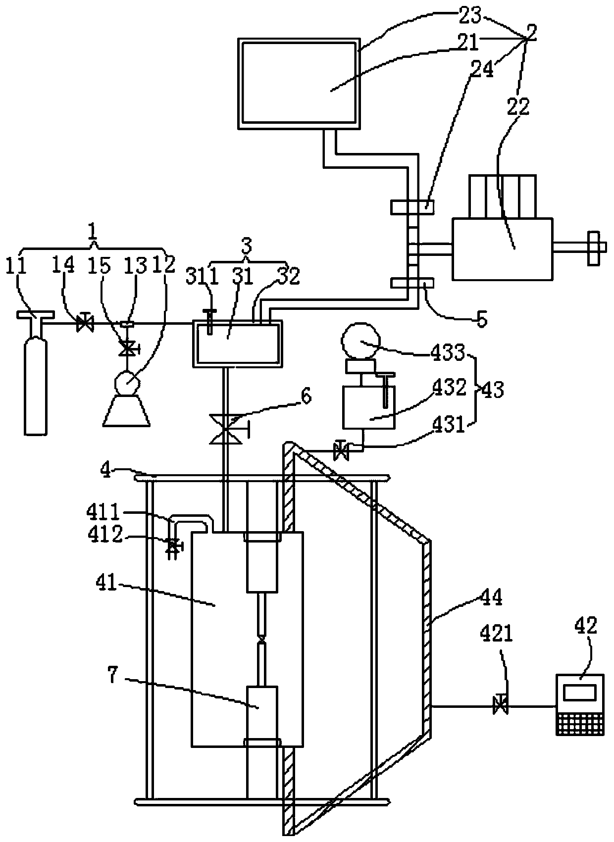
[0033] Such as figure 1As shown, the present embodiment provides a creep fatigue test system, including an air supply mechanism 1, a sodium supply mechanism 2, a sodium storage mechanism 3 and a creep fatigue testing machine 4, and the sodium storage mechanism 3 has a air inlet, sodium inlet and sodium outlet, the gas supply mechanism 1 has an air outlet, the sodium supply mechanism 2 has a sodium outlet, the gas outlet of the gas supply mechanism 1 is connected to the sodium storage mechanism 3 The air inlet of the sodium supply mechanism 2 is connected and communicated with the sodium inlet of the sodium storage mechanism 3, and a first valve 5 is provided at the communication point. The creep fatigue test The machine 4 has a sodium inlet, and the sodium outlet of the sodium storage mechanism 3 is connected with the sodium inlet of the creep fatigue testing machine 4, and a second valve 6 is arranged at the connection between the two, and the creep fatigue testing machine 4 ...

Embodiment 2

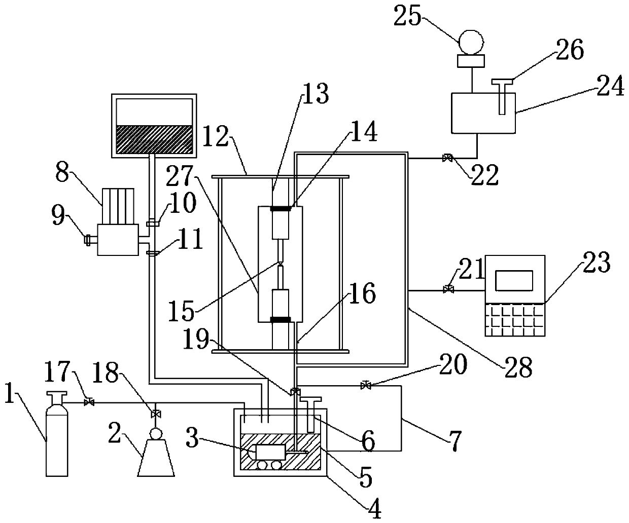
[0049] With embodiment 1, its difference is, as figure 2 As shown, the sodium storage mechanism 3 in the above technical solution also includes a delivery pump 33 and a return pipe 34, the delivery pump 33 is placed at the inner bottom of the second sodium storage tank 31, and its inlet is connected to the second storage tank 31. The sodium tank 31 is connected, and the second sodium storage tank 31 sodium outlet of the outlet is connected to one end in the second sodium storage tank 31, and the sodium inlet of the creep fatigue testing machine 4 is connected to the second valve 6 The connecting part of the second three-way 45 is provided with a second three-way 45, and the remaining interface of the second three-way 45 is connected and communicated with one end of the return pipe 34, and the other end of the return pipe 34 extends to the second sodium storage tank. The interior of the tank 31 is communicated, and the level of the second tee 45 is higher than the level of the...


PUM


Abstract

The invention discloses a creep fatigue test system. The system comprises a gas supply mechanism, a sodium supply mechanism, a sodium storage mechanism and a creep fatigue testing machine. The sodiumstorage mechanism has a gas inlet, a sodium inlet and a sodium outlet which are connected to an internal portion, the gas supply mechanism has a gas outlet, the sodium supply mechanism has a sodium outlet, and the gas outlet of the gas supply mechanism is connected with the gas inlet of the sodium storage mechanism. The sodium outlet of the sodium supply mechanism is connected with the sodium inlet of the sodium storage mechanism, and a first valve is arranged at a connection portion. The creep fatigue testing machine has the sodium inlet, the sodium outlet of the sodium storage mechanism is connected to the sodium inlet of the creep fatigue testing machine, and a second valve is arranged at the connection portion of the two. A workpiece is fixed in the creep fatigue testing machine, and the gas supply mechanism is used to vacuumize the sodium storage mechanism and the creep fatigue testing machine and supply an inert gas into the sodium storage mechanism and the creep fatigue testingmachine. The structure is simple and usage is convenient.

Description

technical field [0001] The invention belongs to the field of creep fatigue test equipment, in particular to a creep fatigue test system with sodium automatic circulation under high temperature environment. Background technique [0002] Existing creep fatigue testing machines are mainly used for tension, compression durability, creep, relaxation tests and low cycle fatigue and creep fatigue tests of metal and non-metallic materials, but in the actual industrial production environment, the parts are in the surrounding Under the action of medium (the most common are gases and liquids), due to a period of chemical changes, electrochemical changes or physical dissolution, damage will occur and corrosion will occur. When performing fatigue tests, due to the time consumed by actual experiments compared with manufacturing The time required for parts to corrode is much shorter, and corrosion is difficult to form. Therefore, the existing fatigue test equipment cannot simulate the tens...

Claims


Application Information

Patent Timeline
Patent Type & Authority Applications(China)
IPC IPC(8): G01N3/56G01N17/00
CPCG01N3/56G01N17/00G01N17/002G01N17/006G01N2203/0071G01N2203/0073G01N2203/024
Inventor 郑小涛陈厚锟喻九阳汪威马琳伟徐建民
Owner WUHAN INSTITUTE OF TECHNOLOGY
Why Eureka
Try Eureka