
Variable flow leaching integration device

A flow and leaching technology, applied in the direction of measuring devices, solid waste removal, instruments, etc., can solve the problems of single flow control, less filling slag, retention, etc., and achieve simple disassembly and assembly of equipment, convenient loading and unloading of slag, and reasonable design Effect

Pending Publication Date: 2019-10-22
云南省环境科学研究院(中国昆明高原湖泊国际研究中心)
View PDF0 Cites 4 Cited by
  • Summary
  • Abstract
  • Description
  • Claims
  • Application Information

AI Technical Summary

Problems solved by technology

[0002] With the sustained and stable development of the national economy, my country's mining industry and smelting industry have developed rapidly. However, due to multiple reasons such as long-term extensive and backward production methods and lagging environmental management in the region, there are a large number of tailings, slag, coal gangue, and smelting waste. The demolition and construction waste of smelters and smelters are piled up randomly, and most of the solid wastes are directly piled up, in direct contact with the surrounding surface soil, and may cause serious harm to the surrounding water bodies, groundwater, and soil after being leached by rainwater and other media. Scientific and targeted understanding of the impact of rainfall intensity and acid rain on the pollutants in the leaching solution produced by a certain solid during the leaching process is particularly necessary to provide leaching data for subsequent solid waste stockpile treatment and risk assessment
[0003] At present, most of the existing leaching devices are still in the laboratory stage, and there are the following problems: 1. The filling height and volume of the leaching column are small, and the amount of filling slag is too small, which is not close to the storage height and the overall packing under natural conditions. Second, the flow control is single, which cannot accurately simulate the actual rainfall under different rainstorm intensities. Third, most of the leaching liquid preparation is completed before the experiment, and it is separated from the whole set of equipment, which cannot realize integrated operation.

Method used


Image

  • Variable flow leaching integration device
  • Variable flow leaching integration device
  • Variable flow leaching integration device

Examples


Embodiment Construction

[0029] The following will clearly and completely describe the technical solutions in the embodiments of the present invention with reference to the accompanying drawings in the embodiments of the present invention. Obviously, the described embodiments are only some, not all, embodiments of the present invention. Based on the embodiments of the present invention, all other embodiments obtained by persons of ordinary skill in the art without making creative efforts belong to the protection scope of the present invention.

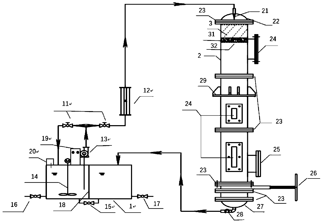
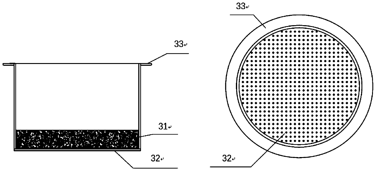
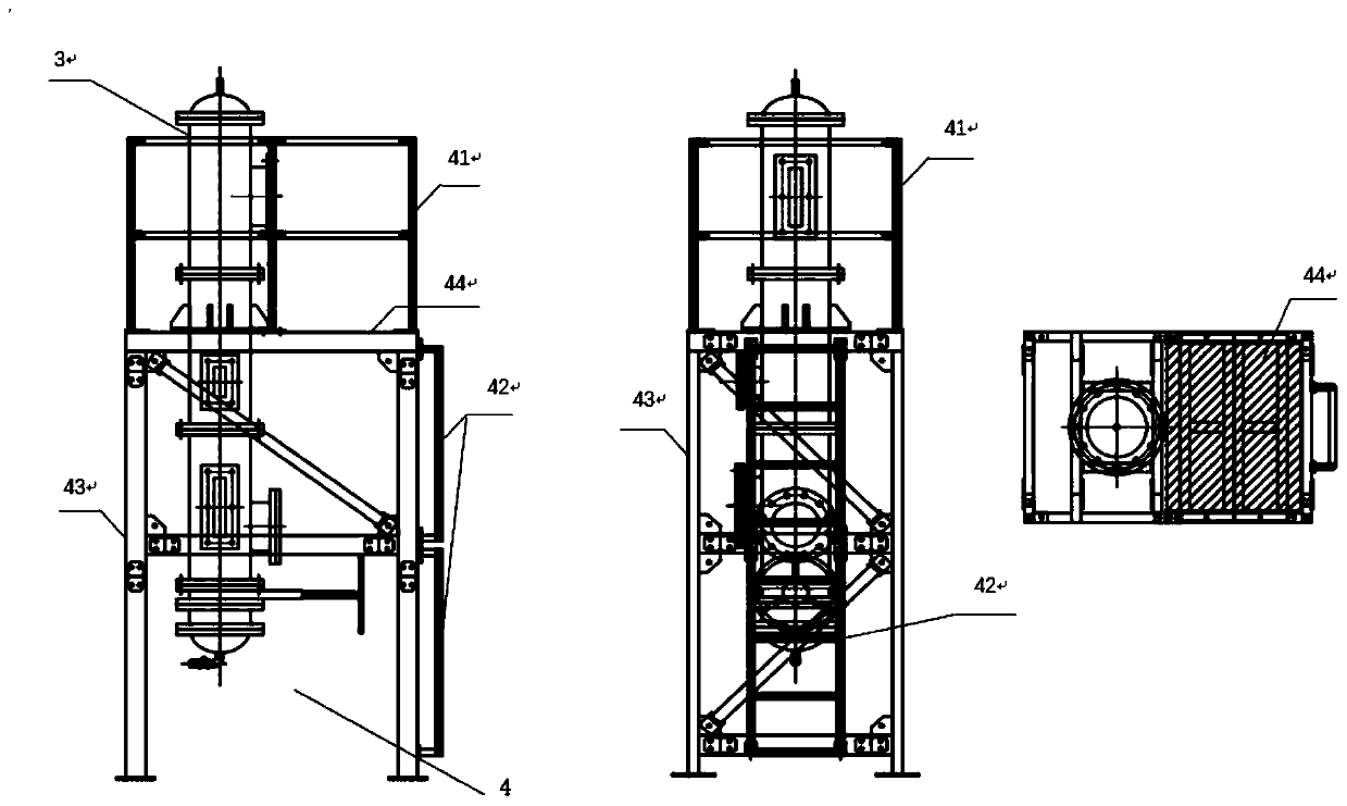
[0030] see Figure 1~3 , a variable flow rate leaching integrated device, including a liquid distribution and receiving area 1, a leaching column 2, a water distribution tank 3 and a support 4, and the liquid mixing and receiving area 1 is separated by a partition 18 in the middle of a square tank It consists of two parts: the left side liquid distribution area and the right side liquid collection area. The online pH monitor 20 is installed on the liquid distr...


PUM

PropertyMeasurementUnit
Radiusaaaaaaaaaa
Wall thicknessaaaaaaaaaa
Heightaaaaaaaaaa

Abstract

The invention discloses a variable flow leaching integration device. The device comprises a fluid preparation and collection area, a leaching column, a water distribution groove and a support. The device has advantages that integration of fluid preparation, fluid inlet and collection is realized; a fluid preparation area has a stirring function; when simulated acid rain is configured, manpower andmixing unevenness can be alleviated; an online PH monitor is installed in the fluid preparation area so as to conveniently and rapidly observe a specific condition of simulated acid rain configuration; a fluid inlet flow can be adjusted, an influence of different rainfall intensities on dissolution of pollutants in different regions can be simulated; a height is changeable, the influence of different high slag heap rainwater infiltration time on the dissolution of the pollutants is studied, and the device is closer to an reality than a laboratory device; an insertion plate valve is arranged to facilitate loading and unloading of slag during engineering, and the slag can be effectively stored when a leaching solution flows out; and a material is resistant to acid and corrosion, use of a certain solid is not limited, and leaching experiments of general industrial solid wastes, hazardous wastes, urban construction wastes, soil and the like can be researched.

Description

technical field [0001] The invention relates to a leaching integrated device, in particular to a variable flow leaching integrated device, which belongs to the technical field of industrial waste residue and soil treatment. Background technique [0002] With the sustained and stable development of the national economy, my country's mining industry and smelting industry have developed rapidly. However, due to multiple reasons such as long-term extensive and backward production methods and lagging environmental management in the region, there are a large number of tailings, slag, coal gangue, and smelting waste. The demolition and construction waste of smelters and smelters are piled up randomly, and most of the solid wastes are directly piled up, in direct contact with the surrounding surface soil, and may cause serious harm to the surrounding water bodies, groundwater, and soil after being leached by rainwater and other media. Scientific and targeted understanding of the impac...

Claims


Application Information

Patent Timeline
IPC IPC(8): G01N33/00B09B3/00
CPCB09B3/00G01N33/00Y02W30/58
Inventor 王统吴学勇陈晨牛学奎王舒婷王宏
Owner 云南省环境科学研究院(中国昆明高原湖泊国际研究中心)
Learn More