
Patsnap Eureka
For R&D, Patsnap Eureka makes reading and utilizing patents & technical documents easy.
Patsnap Eureka AIR
Designed for self-driven R&D workflows. Generate viable solutions, solve complex R&D challenges, empower your innovation with AI.

Patsnap Eureka Materials
Designed for material experts only. Revolutionize your material R&D, from search, analyze, to developing new materials.

TechResearch
Generate reliable direction feasibility study reports for your R&D in just a few steps.

TechSeek
Discover and master advanced knowledge NOW. Basics, ideas, possibilities, all at once.

TechMind
As an expert in R&D Theories, TechMind can generates customized viable solutions instantly.

TechRisk
Analyze your overall solution with one click, know your potential R&D risks in advance.

TechMonitor
Get weekly tech updates, stay abreast of the latest tech innovations and key insights.
Rotor splicing block assembly, linear motor rotor, linear motor, machine tool and production method of linear motor rotor
A technology of linear motors and block components, which is applied in the direction of electric components, manufacturing motor generators, and the shape/style/structure of winding conductors, which can solve the problems of poor cooling effect of iron core windings, rapid temperature rise of cooling liquid, and immobility of cooling pipes The sub-gear part is completely wrapped, etc., so as to achieve the effect of simple winding processing, saving installation space, and simple production process
- Summary
- Abstract
- Description
- Claims
- Application Information
AI Technical Summary
Problems solved by technology
Method used
Image

Examples
Embodiment 1
[0041] This example refers to figure 1 The coordinate system shown is described.
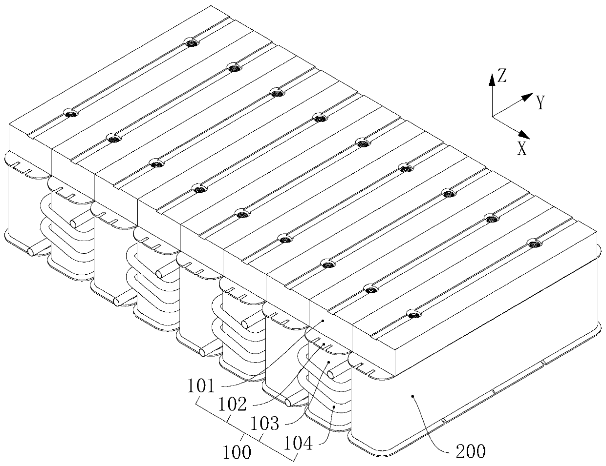
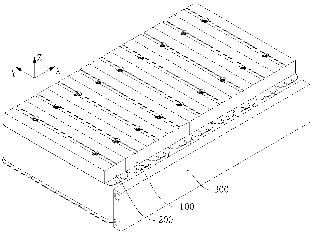
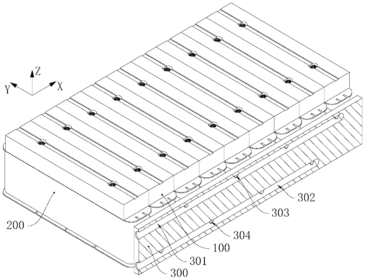
[0042] Please refer to Figure 1 to Figure 4 , the machine tool of this embodiment includes the linear motor of this embodiment, the linear motor of this embodiment adopts the linear motor mover of this embodiment, the linear motor mover of this embodiment includes a block unit and a cooling pipe body 300, each block The block units are sequentially spliced along the X-axis direction, and each block unit includes a first block unit 100 and a second block unit 200, and each first block unit 100 and each second block unit 200 are alternately distributed in the X-axis direction , the first block unit 100 is the mover block assembly of this embodiment.
[0043] The production method of the linear motor mover of this embodiment is used to produce the linear motor mover of this embodiment.
[0044] Please refer to Image 6 , the mover block assembly of this embodiment includes a block core 101, an...
Embodiment 2
[0053] Please refer to Figure 7 Each block unit of this embodiment adopts the aforementioned mover block assemblies, each mover block assembly is sequentially spliced along the X-axis direction, and the iron core splicing parts 1011 of adjacent mover block assemblies are connected.
[0054] Please refer to Figure 7 , in two adjacent block units, the helical coils of the two cooling pipes 104 are distributed alternately in the direction of the Z axis. Each block unit adopts the mover block assembly of this embodiment, so that each block unit can be well cooled; the spiral turns of each adjacent cooling pipe 104 are staggered in the Z-axis direction, which is convenient for saving installation space. It is beneficial to the compact structure of the mover of the linear motor.
[0055] Compared with the scheme of embodiment 1 of the production method of mover block assembly, linear motor mover, linear motor, machine tool and linear motor mover, this embodiment is suitable fo...
PUM
 Abstract
Description
Claims
Application Information
 - R&D Engineer
- R&D Manager
- IP Professional
- Industry Leading Data Capabilities
- Powerful AI technology
- Patent DNA Extraction
Browse by: Latest US Patents, China's latest patents, Technical Efficacy Thesaurus, Application Domain, Technology Topic, Popular Technical Reports.
© 2024 PatSnap. All rights reserved.Legal|Privacy policy|Modern Slavery Act Transparency Statement|Sitemap|About US| Contact US: help@patsnap.com