
Efficient chemical reaction kettle

A technology for chemical reaction and reactor body, applied in the field of high-efficiency chemical reactors, can solve the problems of slow reaction efficiency of the reactor, inconvenient material discharge, etc., and achieve the effect of increasing the stirring effect and the effect of fast reaction efficiency.

Inactive Publication Date: 2019-10-25
罗运宏
View PDF9 Cites 0 Cited by
  • Summary
  • Abstract
  • Description
  • Claims
  • Application Information

AI Technical Summary

Problems solved by technology

[0003] The purpose of the present invention is to provide a high-efficiency chemical reaction kettle, which has the advantages of fast reaction efficiency and convenient discharge of materials, and solves the problem of slow reaction efficiency of the reaction kettle and inconvenient discharge of materials

Method used


Image

  • Efficient chemical reaction kettle
  • Efficient chemical reaction kettle
  • Efficient chemical reaction kettle

Examples


Embodiment 1

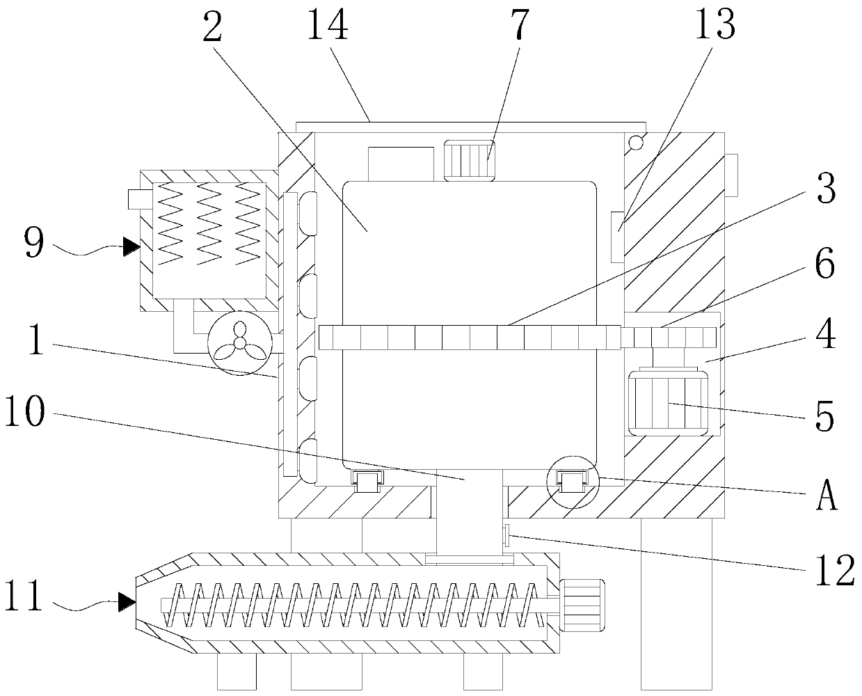
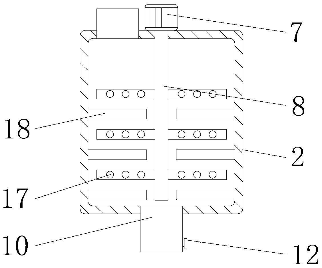
[0022] see Figure 1-5 , a high-efficiency chemical reaction kettle, including a box body 1, a temperature sensor 13 is fixedly connected inside the box body 1, through the temperature sensor 13, the effect of temperature detection in the box body 1 is achieved, and the effect of mixing is avoided. The right side of the top of the body 1 is movably connected with a cover plate 14 through a rotating shaft. Through the cover plate 14, the effect of sealing the box body 1 is achieved to avoid heat dissipation. The bottom of the box body 1 and the discharge mechanism 11 are equipped with movable Mechanism, the moving structure includes rollers installed on both sides of the bottom of the box 1 and a motor installed on the left side of the bottom of the box 1. The moving method is: start the motor, and the output end of the motor drives the rollers on both sides of the bottom of the box 1 through a belt. Rotate, so as to realize the movement of the box body 1, and the motor can be ...

Embodiment 2

[0024] see Figure 1-5, a high-efficiency chemical reaction kettle, including a box body 1, a temperature sensor 13 is fixedly connected inside the box body 1, through the temperature sensor 13, the effect of temperature detection in the box body 1 is achieved, and the effect of mixing is avoided. The right side of the top of the body 1 is movably connected with a cover plate 14 through a rotating shaft. Through the cover plate 14, the effect of sealing the box body 1 is achieved to avoid heat dissipation. The bottom of the box body 1 and the discharge mechanism 11 are equipped with movable Mechanism, the moving mechanism is the rollers installed on both sides of the bottom of the box body 1, and its movement method is: people push the box body 1, so that the rollers rotate and drive the box body 1 to move, and the inside of the box body 1 is provided with a reaction kettle body 2 , the left side of the top of the reactor body 2 is connected with a filling pipe, both sides of ...


PUM


Abstract

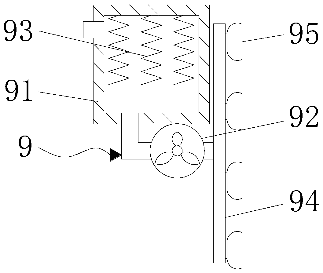
The invention discloses an efficient chemical reaction kettle. The efficient chemical reaction kettle includes a box body, the box body is internally provided with a reaction kettle body, a first gearsleeves the surface of the reaction kettle body, a groove is formed in the right side of the surface of the box body, the groove is internally and fixedly connected with a first motor, a rotating shaft of the first motor is fixedly connected with a second gear, the first gear is engaged with the second gear, and the top of the reaction kettle body is fixedly connected with a second motor. According to the efficient chemical reaction kettle, by arranging the box body, the effect of placement of the reaction kettle body is achieved, through the reaction kettle body, the effect of material placement is achieved, through the first gear, the first motor and the second gear, the effect that the reaction kettle body is driven to rotate is achieved, through the second motor and a first stirring rod, the effect of material stirring is achieved, through a heating mechanism, the effect of heating of the reaction kettle body is achieved, the reaction kettle is fast in reaction efficiency, material discharging is convenient, and the reaction kettle is convenient to use.

Description

technical field [0001] The invention relates to the technical field of reactors, in particular to a high-efficiency chemical reactor. Background technique [0002] The broad understanding of the reactor is a container with physical or chemical reactions. Through the structural design and parameter configuration of the container, the heating, evaporation, cooling and low-speed mixing functions required by the process are realized. The reactor is widely used in petroleum, chemical, Rubber, pesticides, dyes, medicines, food, pressure vessels used to complete vulcanization, nitration, hydrogenation, alkylation, polymerization, condensation and other processes, such as reactors, reaction pots, decomposition pots, polymerization kettles, etc.; materials generally have carbon Manganese steel, stainless steel, zirconium, nickel-based (Hastelloy, Monel, Inconel) alloys and other composite materials need to mix and stir a variety of raw materials in chemical reactors to make them a mi...

Claims


Application Information

Patent Timeline
IPC IPC(8): B01J19/28
CPCB01J19/0013B01J19/0053B01J19/0066B01J19/28B01J2219/00087
Inventor 不公告发明人
Owner 罗运宏
Learn More