
Construction method used for tunnel road surface water seepage governance

A construction method and tunnel technology, which is applied in the construction field of tunnel pavement water seepage control, can solve the problems of limited drainage area, reduced vehicle traction, and reduced service life of tunnels, etc.

Inactive Publication Date: 2019-10-25
中交二公局第四工程有限公司
View PDF5 Cites 3 Cited by
  • Summary
  • Abstract
  • Description
  • Claims
  • Application Information

AI Technical Summary

Problems solved by technology

[0003] For water seepage and water leakage in tunnels in operation, the lining of the tunnel will be damaged, the steel materials used to build the tunnel will also be corroded, some communication, lighting and other infrastructure of the tunnel will also be damaged, and the stability of the tunnel line will be damaged. Sexuality will have a serious impact, reducing the traction of the vehicle, and in severe cases, driving will be interrupted, which will seriously affect the safe operation of traffic and reduce the service life of the tunnel.
[0004] Using the traditional notch method to control water seepage is more effective for areas with clear seepage points, but the notch method is not effective in solving large-scale seepage due to the limited drainage area, and the pavement notch will affect the overall appearance and driving comfort. There are many deficiencies

Method used


Image

  • Construction method used for tunnel road surface water seepage governance
  • Construction method used for tunnel road surface water seepage governance
  • Construction method used for tunnel road surface water seepage governance

Examples


Embodiment Construction

[0024] The present invention will be further described below in conjunction with the accompanying drawings and specific embodiments.

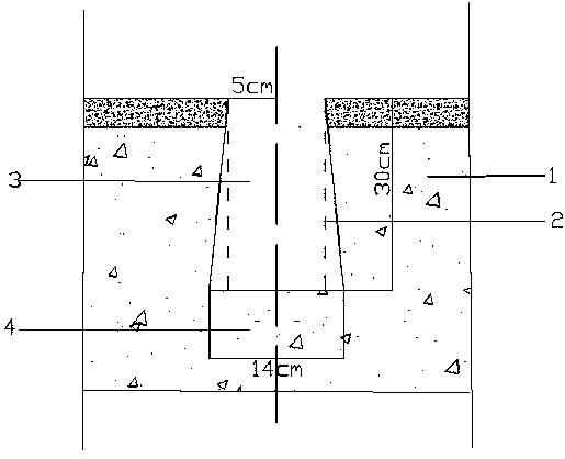
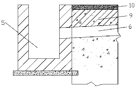
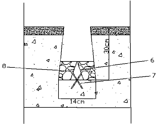
[0025] Such as figure 1 As shown, a construction method for the control of water seepage on the tunnel pavement, the construction method adopts the method of forming holes with angle steel for drainage, finds the water outlet point and the scope of water seepage, and sprays water on the site of water seepage on the original concrete pavement 1 of the tunnel Lay dry PC32.5# cement, observe the infiltration of the road surface, take the central point of the road surface with obvious water leakage or large-scale infiltration range as the water seepage point, and place 5cm on both sides of the water seepage point determined by the original concrete road surface 1 of the tunnel Carry out the cutting of transverse driving lane, form described cutting groove 2, further carry out groove on the basis of described cutting groove 2, form described trapezo...


PUM


Abstract

The invention relates to the field of road surface water seepage governance and discloses a construction method used for tunnel road surface water seepage governance. According to the disclosed construction method used for tunnel road surface water seepage governance, guiding drainage is performed by adopting an angle steel hole forming method, according to specific construction steps, a water outflow point and a water seepage range are looked over and determined; groove cutting is performed; a trapezoidal groove is formed; groove forming treatment is performed, and the trapezoidal groove is made to communicate with a water draining ditch; angle steel is arranged in the trapezoidal groove; filling of a gravel layer is performed; and road surface layer sealing is performed. According to theconstruction method, the angle steel is adopted for drainage, and the angle steel is firm in material, and not prone to damage due to vibration caused by a vehicle; expanding bolts are fixed to the two sides of the angle steel, but not the top of the angle steel in order to avoid that concrete damage is caused by the fact that construction is not proper, the angle steel is vibrated and bounces out, tires of passing vehicles are punctured, and accidents are caused; and the positions around the angle steel are filled with the gravel layer in order to prevent that due to the fact that the wateramount is too large or due to other factors, water flow reversely seeps, and discharging into the water draining ditch in time through a hole gap of the gravel layer can be achieved.

Description

technical field [0001] The invention relates to the field of pavement water seepage control, in particular to a construction method for tunnel pavement water seepage control. Background technique [0002] Tunnel water damage refers to the disturbance and harm of water encountered during the construction or operation of tunnels. Tunnel water damage during construction mainly refers to the damage caused by the groundwater or part of the surface water in the surrounding rock of the tunnel entering the tunnel in the form of leakage or gushing. [0003] For water seepage and water leakage in tunnels in operation, the lining of the tunnel will be damaged, the steel materials used to build the tunnel will also be corroded, some communication, lighting and other infrastructure of the tunnel will also be damaged, and the stability of the tunnel line will be damaged. Sexuality will have a serious impact, reducing the traction of the vehicle, and in severe cases, driving will be inter...

Claims


Application Information

Patent Timeline
IPC IPC(8): E01C23/09
CPCE01C23/096
Inventor 刘宏伟阮明和刘光军陈永军黄辉程伟峰曹天伟张加志周恒玉杨旭光
Owner 中交二公局第四工程有限公司
Learn More