Quantified fluorescence microscopy

a fluorescence microscopy and quantitative technology, applied in the field of microscopy, can solve the problems of difficult comparison, increased difficulty in comparing, and different fluorescence microscopy of specimens, and achieve the effect of stable fluorescence material and fine features

Inactive Publication Date: 2006-01-10
AFFYMETRIX INC
View PDF45 Cites 24 Cited by
  • Summary
  • Abstract
  • Description
  • Claims
  • Application Information

AI Technical Summary

Benefits of technology

[0027]In a preferred embodiment, a fluorescent calibration tool is built with a suitably fluorescent solid surface layer of constant thickness that is opaque, made of organic material or inorganic material, carried on a suitable support. For materials that are not naturally opaque, dyes or pigments are added. A very thin metal layer is subsequently deposited on the opaque fluorescent material and covered with a layer of photo-resist. An appropriate pattern is then imaged on the photo-resist and chemically etched. The resulting fluorescent pattern showing through the etched openings has extremely fine features because the metal layer is as little as a fraction of a micron thick, preferably about 100 to 300 Angstrom thick. The pattern-creating process can be identical to the process used to create integrated circuits. Presently that technology enables the formation of features as narrow as 0.2 micron width lines separated by spaces of the same dimension.
[0028]In the calibration tool, the fluorescence is caused to be a surface emission phenomenon, which permits reliable focusing and fluorescence calibration, that can be used as a standard, and enable all instruments to be set to the same standard. Preferably, the calibration tool uses a very stable fluorescing material, that is insensitive to photobleaching.

Problems solved by technology
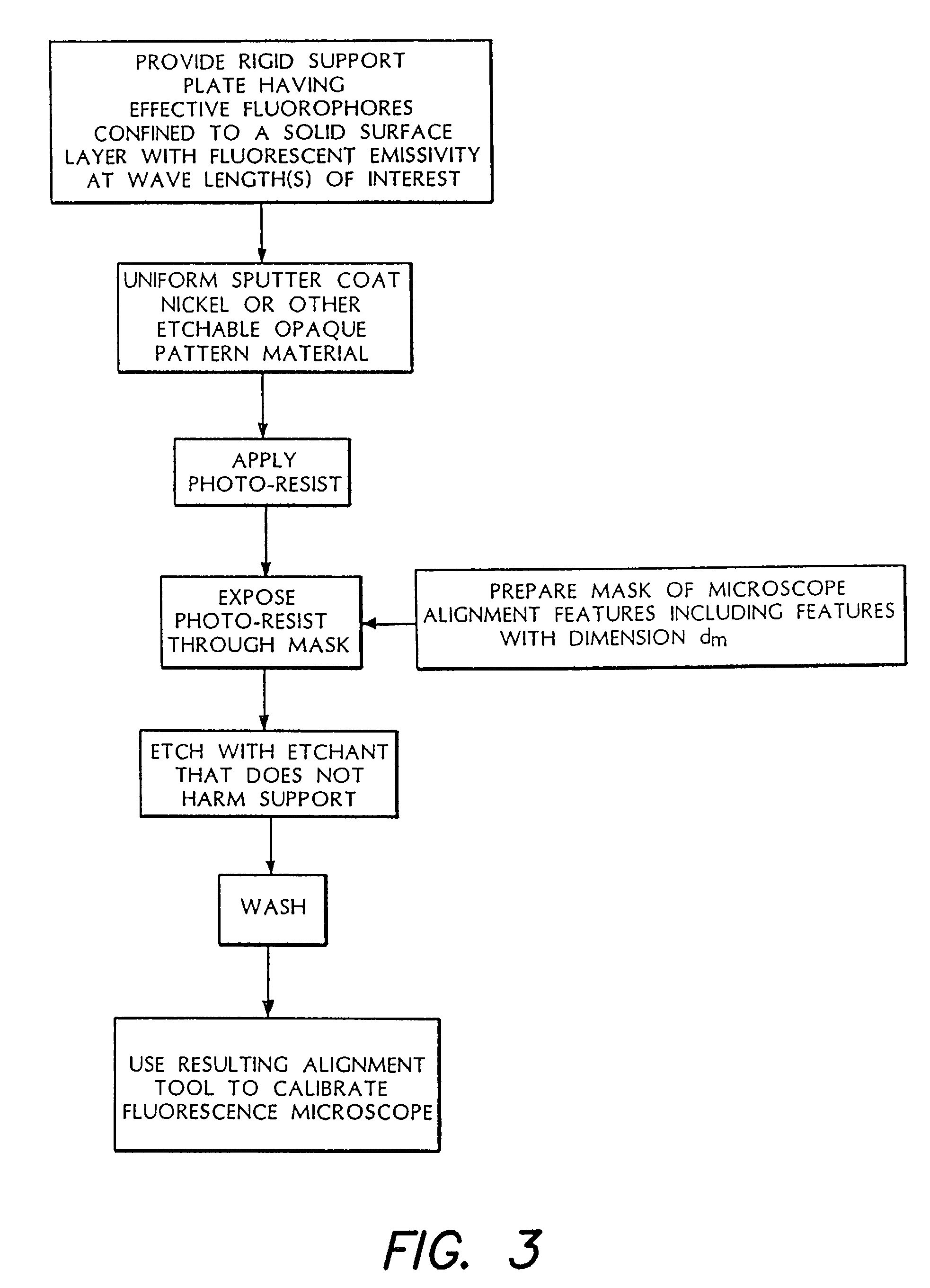
Fluorescent microscopy of specimens is different from and more demanding than conventional microscopy because it is based on relatively low-level fluorescent emissions excited by illumination of the specimen, typically employing confocal arrangements for detecting the relatively weak signal through a pin hole or the like.
This introduces significant complications, as fluorescence involves an excited photochemical effect, to produce a voltage or signal level in the detector, that introduces signal to noise ratio considerations that interact with measurements of the various optical components involved in the calibration.
It has been an unsolved problem, to find a calibration target that adequately simulates the fluorescent activity which it is desired to quantify over a broad range of instruments and conditions of use.
As the dimensions of individual specimens to be imaged become increasingly smaller as microarray technology advances, the significance of not having a suitable calibration tool has become increasingly severe.
The difficulties for fluorescent microscopy is that, without the desired degree of calibration, it becomes difficult to compare the results obtained in biological or other research performed with different instruments, thus creating serious difficulties in comparing and coordinating the results of different laboratories, whether the laboratories be at different institutions, or separate laboratory facilities within the same institution.
Likewise, even with a given instrument, the uncertainties of calibration can introduce errors in the measurement of important actions such as proportional expression, etc.
In particular the lack of good reference and calibration is felt at the forefront of research where results are so new and there has been insufficient time or experience to generate reliable standards.
Existing calibration tools for conventional microscopy do not satisfactorily fill the needs of fluorescence microscopy.
This is unsatisfactory for calibration with respect to instruments employing conventional 5 micron spot size and is an order of magnitude greater than required to evaluate optical spots that are ½ micron in diameter, achievable with a microscope having an 0.7 NA objective in air, or ¼ micron diameter achievable with a 1.4 NA, oil immersion objective.
The relatively large thickness of the fluorescent layer poses problems of edge definition, particularly because the fluorescent rays emit at acute angles to the surface and can be blocked by the edges of the material, or on the other hand, the edges themselves fluoresce, to produce confusion.
The fluorescent radiation emitted from this volume causes focus to be difficult to define accurately and hence is an unsatisfactory standard for many purposes.

Method used


Image

  • Quantified fluorescence microscopy
  • Quantified fluorescence microscopy
  • Quantified fluorescence microscopy

Examples


Embodiment Construction

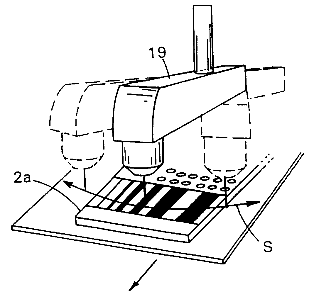
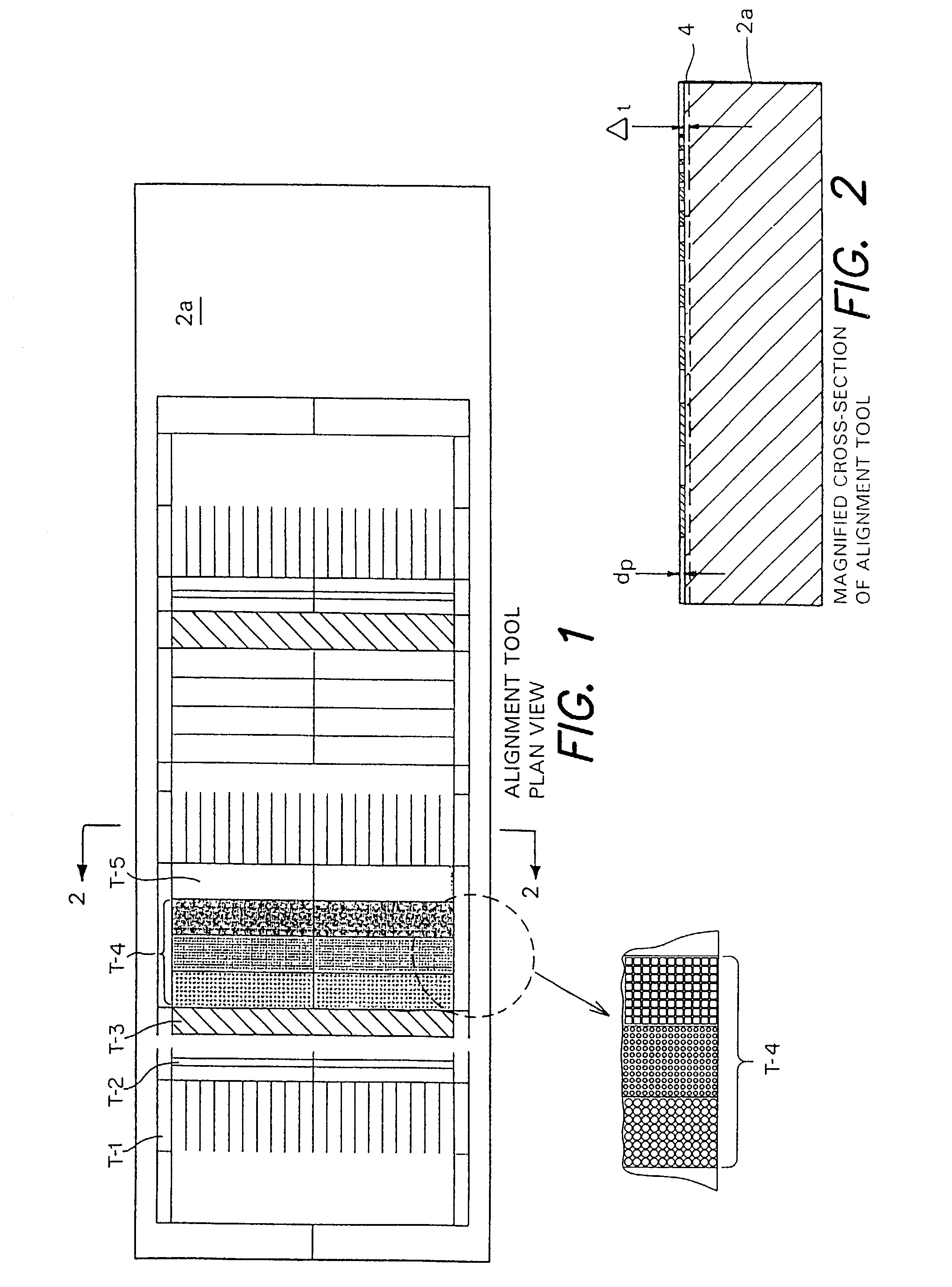
[0052]Referring to FIGS. 1 and 2, the alignment tool 2a comprises a generally planar rigid member carrying on its face a detailed pattern of optical features suitable for calibration of the instrument. The rigid member is typically of the same dimensions as the microscope slide, microarray chip or other object to be examined, to fit in the same position on the instrument. The optical features of the alignment tool include lines and circular dots of various dimensions to emulate the various sizes of dots and linear features of biological or other material to be examined. The finest features have dimensions of the order of 1 micron or less to suitably calibrate for detection of features of a few micron dimensions or less.

[0053]The calibration tool shown in FIGS. 1 and 2 includes regions T-1, T-2, T-3, T-4, and T-5. Region T-1 includes a set of “barcode” lines having thickness 2 micron, 4 micron, 6 micron, 8 micron, 10 micron, and 12 micron, separated by twice their size. Region T-2 in...


PUM

PropertyMeasurementUnit
thicknessaaaaaaaaaa
thicknessaaaaaaaaaa
thicknessaaaaaaaaaa

Abstract

The present invention relates to calibration apparatuses, methods or tools used in microscopy. A calibration tool for fluorescent microscopy includes a support, a solid surface layer including a fluorescent material, and a thin opaque mask of non-fluorescent material defining reference feature openings having selected dimensions exposing portions of the surface layer. A first type of the calibration tool may include an adhesion promoter facilitating contact between the surface of the support and the solid surface layer including the fluorescent material, which is in contact with the thin opaque mask. A second type of the calibration tool may include the thin opaque mask fabricated (with or without an adhesion promoter) onto the support, and the solid surface layer including the fluorescent material located on the thin opaque mask.

Description

[0001]This application is a continuation of co-pending PCT Application PCT / US01 / 04336, filed on Feb. 9, 2001, and is a continuation-in-part of U.S. patent application Ser. No. 09 / 500,626, filed on Feb. 9, 2000, now U.S. Pat. No. 6,472,671. The disclosure of the above-mentioned applications is considered part of, and is incorporated by reference in the disclosure of this application.TECHNICAL FIELD[0002]This invention relates to microscopy and more particularly to calibrating a position of a sample with respect to optical elements of a microscope and / or to calibrating fluorescence detection in microscopes.BACKGROUND[0003]Testing or calibration targets are employed to evaluate system performance of conventional microscopes. These are used to establish a baseline between different microscope systems and to characterize image quality in terms of its conventional components: resolution, contrast, depth of field and distortion. Common offerings for conventional microscopy are the USAF Fie...

Claims


Application Information

Patent Timeline
Patent Type & Authority Patents(United States)
IPC IPC(8): G12B13/00G02B21/00B01L3/02C40B60/14G01J3/30G01N21/27G01N21/64G01N35/10G02B21/16G02B21/34
CPCB01L3/0244G01N21/274G01N21/278G01N21/64G01N21/6452G01N21/6458G02B21/16G02B21/34B01L3/0251Y10T428/24355B82Y30/00C40B60/14G01N35/1065G01N2035/1034G01N2035/1037B01J2219/00364B01J2219/00387B01J2219/00527B01J2219/00585B01J2219/0059B01J2219/00596B01J2219/00605B01J2219/00612B01J2219/00659B01J2219/00677B01J2219/00691
Inventor MONTAGU, JEAN I.
Owner AFFYMETRIX INC
Why Eureka
Try Eureka