
Power transmission line simulation method and system

A technology of transmission lines and simulation methods, applied in the field of power systems, can solve the problem that the electromagnetic transient simulation model of transmission lines cannot effectively take into account the efficiency and accuracy of simulation

Active Publication Date: 2019-10-25
NORTH CHINA ELECTRIC POWER UNIV (BAODING)
View PDF7 Cites 2 Cited by
  • Summary
  • Abstract
  • Description
  • Claims
  • Application Information

AI Technical Summary

Problems solved by technology

[0004] The purpose of the present invention is to provide a transmission line simulation method and system, which solves the problem that the existing transmission line electromagnetic transient simulation model cannot effectively take into account the efficiency and accuracy of simulation

Method used


Image

  • Power transmission line simulation method and system
  • Power transmission line simulation method and system
  • Power transmission line simulation method and system

Examples


Embodiment 1

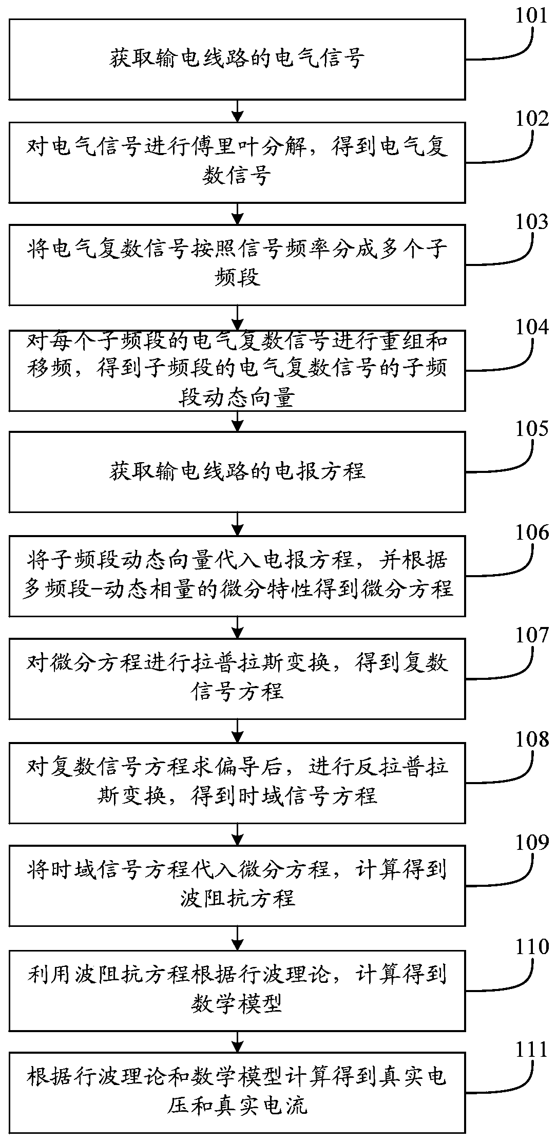
[0116] This embodiment provides a transmission line simulation method. The transmission line simulation method of the present embodiment calculates the mathematical model by the multi-band dynamic phasor method, and the principle of the multi-band dynamic phasor method includes:

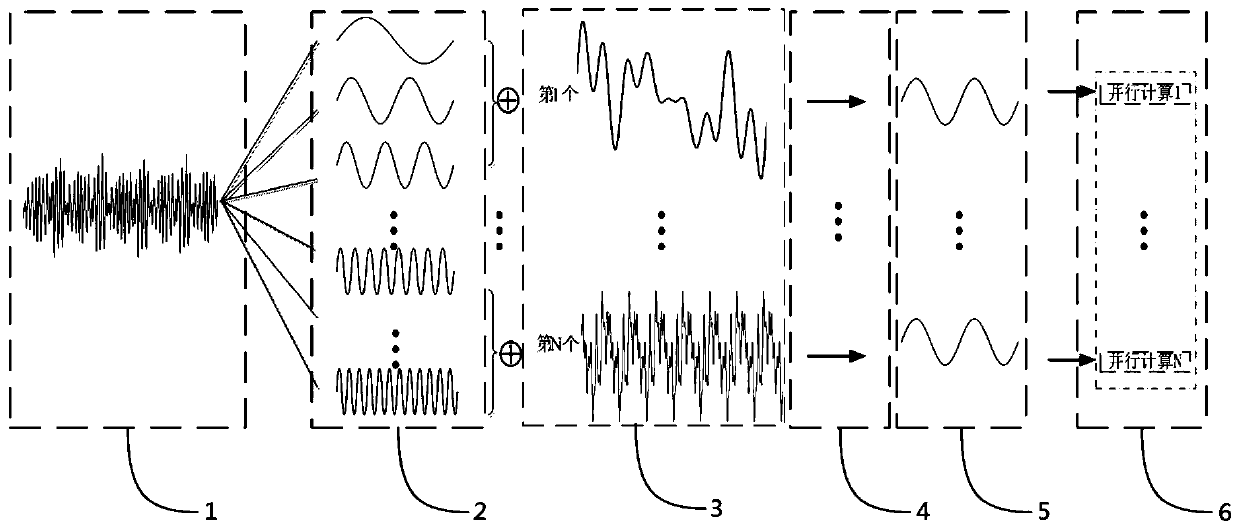
[0117] (1) Decompose and recombine the frequency of electrical signals:

[0118] Voltage, current, etc. in the power system can be regarded as periodic electrical signals. For a fundamental period T 0 The electrical signal x(τ), in any period τ∈(t-T 0 ,t], t represents any time of the period τ, and the Fourier decomposition of the complex number form of the electrical signal is:

[0119]

[0120] In the formula (1), X(t) is the complex number form of the electrical signal X(τ), which is defined as an electrical complex signal; h represents the harmonic order of the Fourier series; X h (t) is the hth-order Fourier coefficient, that is, the h-order "dynamic phasor", that is, the Fourier coeffici...

Embodiment 2

[0206] This embodiment provides a power transmission line simulation system, and the power transmission line in Embodiment 2 is a long power transmission line. Figure 7 It is a structural diagram of the power transmission line simulation system provided by Embodiment 2 of the present invention. See Figure 7, a power transmission line simulation system, including:

[0207] The obtaining module 201 is used to obtain the electrical signal of the transmission line; the electrical signal includes: a voltage signal and a current signal. The continuous time domain signals of long transmission lines are current signal i(x, t) and voltage signal u(x, t).

[0208] The Fourier decomposition module 202 is used to perform Fourier decomposition on the electrical signal to obtain the electrical complex signal.

[0209]The Fourier decomposition module 202 includes: a voltage Fourier decomposition unit, which is used to carry out Fourier decomposition to the voltage signal of the electrical...


PUM


Abstract

The invention discloses a power transmission line simulation method and system, and relates to the technical field of power systems. The method comprises the following steps: acquiring an electrical signal, performing Fourier decomposition, dividing the electrical signal into a plurality of sub-bands according to a signal frequency, and performing recombination and frequency shift to obtain sub-band dynamic vectors; substituting the sub-band dynamic vectors into the obtained telegram equation to obtain a differential equation; performing Laplace transformation, partial derivative solving and inverse Laplace transformation on the differential equation in sequence to obtain a time domain signal equation; substituting the time domain signal equation into a differential equation, and calculating to obtain a mathematical model according to a traveling wave theory; and calculating to obtain real voltage and current according to a traveling wave theory and a mathematical model. Due to the fact that the sub-band dynamic vectors of the electric complex signals are the signals with the bandwidth, and the bandwidth meets the narrow-band condition, large-step simulation can be adopted to improve the simulation speed, and the power transmission line simulation method can effectively give consideration to the simulation efficiency and precision.

Description

technical field [0001] The invention relates to the technical field of electric power systems, in particular to a transmission line simulation method and system. Background technique [0002] Transmission lines are the most common and widely used components in power systems. Traditional line models are time-domain instantaneous value models derived from traveling wave characteristic equations. Common line models are mainly divided into two categories: one is lumped parameter Models, including the π-type cascade model; the other is the distributed parameter model, including: Bergeron model, Dommel model and J.R.Marti model, etc. However, the π-type cascade model, Bergeron model, Dommel model and J.R.Marti model are all instantaneous value models in the time domain, the simulation calculation step size is small, the simulation efficiency is low, and it is not suitable for analysis and calculation of large-scale power systems. The traditional dynamic phasor model of transmissi...

Claims


Application Information

Patent Timeline
IPC IPC(8): G06F17/50G06F17/11G06F17/13H02J3/00
CPCG06F17/11G06F17/13H02J3/00G06F2111/10G06F30/20H02J2203/20
Inventor 姚蜀军汪燕蔡焱蒙
Owner NORTH CHINA ELECTRIC POWER UNIV (BAODING)
Learn More