
Coordinated control method for wind power DC transmission system under single pole blocking fault

A single-pole blocking and coordinated control technology, applied in wind power generation, AC network voltage adjustment, electrical components, etc., can solve the problem of not fully utilizing the non-fault pole reactive power adjustment capabilities of doubly-fed wind turbines and converter stations in the sending end system And other issues

Active Publication Date: 2019-10-25
CHONGQING UNIV
View PDF2 Cites 5 Cited by
  • Summary
  • Abstract
  • Description
  • Claims
  • Application Information

AI Technical Summary

Problems solved by technology

[0006] Literature (2) slows down the triggering process of DC blocking by improving the emergency shutdown strategy for triggering DC blocking, changing the triggering sequence of protection measures, and cooperating with the safety control system to suppress the transient overvoltage of the grid-connected bus at the sending end, in order to achieve Guarantee the stable operation of wind turbines, but do not give full play to the reactive power adjustment capabilities of doubly-fed wind turbines and non-faulty poles of converter stations in the sending-end system

Method used


Image

  • Coordinated control method for wind power DC transmission system under single pole blocking fault
  • Coordinated control method for wind power DC transmission system under single pole blocking fault
  • Coordinated control method for wind power DC transmission system under single pole blocking fault

Examples


Embodiment Construction

[0057] Specific embodiments of the present invention will be described in detail below in conjunction with the accompanying drawings.

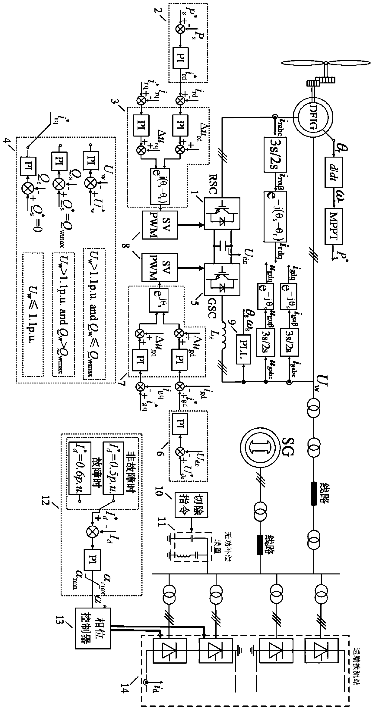
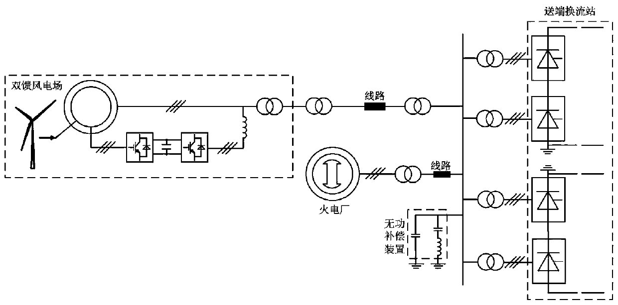
[0058] figure 1 It shows the structural block diagram of the coordinated control method of the wind power DC transmission system under the single-pole blocking fault. It includes the control objects: the generator-side converter 1, the generator-side d-axis current reference value calculation module 2, and the generator-side q-axis current reference value calculation module 3. Machine-side current control module 4, grid-side converter 5, grid-side d-axis current reference value calculation module 6, grid-side current control module 7, space vector modulation 8, phase-locked loop 9, reactive power compensation device removal controller 10. A reactive power compensation device 11, a converter station firing angle calculation module 12, a converter station phase controller 13, and a converter valve 14.

[0059] figure 2 It is a schematic diagr...


PUM


Abstract

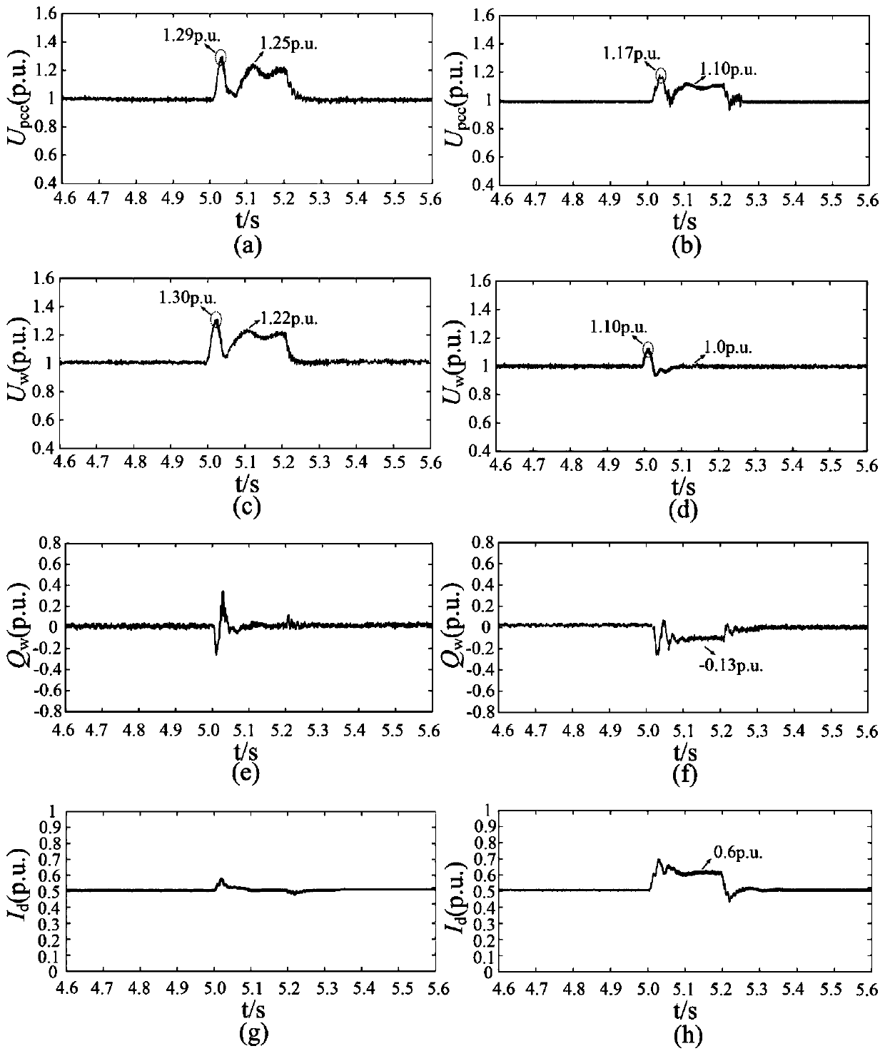
The invention discloses a coordinated control method for a wind power DC transmission system under a single pole blocking fault. The method is characterized in that control of a rectifier station non-faulty pole converter, a matched converter station reactive power compensation device, a doubly-fed wind turbine network side converter and a machine side converter is referred, the control strategy of the doubly-fed wind turbine network side converter is that calculated ird and irq are respectively sent to an inner loop control link of a rotor side converter to obtain a control voltage under a synchronous speed rotating coordinate system, the control voltage is subjected to coordinate transformation to be a control voltage under a static two-phase alpha and beta coordinate axis system, the control voltage and a DC bus voltage are subjected to space vector modulation to generate a rotor-side converter PWM driving signal to suppress a machine terminal overvoltage. The method is advantaged in that when a system has a single-pole blocking fault, a transmission end converter station, the reactive power compensation device and a DFIG wind farm make full use of the reactive power adjustmentcapability to minimize the fault overvoltages at a common connection point of a transmission end and a DFIG wind farm machine terminal to improve system security, stability and fault traversal capabilities.

Description

technical field [0001] The invention belongs to the field of new energy power generation, and in particular relates to a coordinated fault ride-through control method for a sending end system when a single-pole blocking fault occurs in a wind power DC sending system. Background technique [0002] In recent years, due to the increase in power demand and the enhancement of environmental protection awareness, vigorously developing renewable energy represented by wind power has become one of the important choices to ensure the sustainable development of energy and power in our country. However, my country's wind energy resources are mostly distributed in the northeast, northwest, and northern regions of North China (hereinafter referred to as the "Three Norths" region), and the local consumption capacity of wind power in these regions is very limited, and my country's load centers are mainly located in densely populated and economically developed regions. Eastern and central regi...

Claims


Application Information

Patent Timeline
IPC IPC(8): H02J3/38H02J3/16
CPCH02J3/386H02J3/16Y02E10/76Y02E40/30
Inventor 姚骏张田孙鹏刘凯汪军骆悦
Owner CHONGQING UNIV
Learn More