Manufacturing method for manmade rock sample for simulating real form of hydraulic fracturing crack

A technology of hydraulic fracturing and production methods, which is applied in the fields of earthwork drilling, data processing application, measurement, etc. It can solve the problem that the strength of slabs cannot reach the interaction between fracturing construction and formation pressure, the inability to obtain artificial rock samples, and the deviation of mechanical properties And other issues

Inactive Publication Date: 2019-10-29
SOUTHWEST PETROLEUM UNIV
View PDF6 Cites 12 Cited by
  • Summary
  • Abstract
  • Description
  • Claims
  • Application Information

AI Technical Summary

Problems solved by technology

[0007] Although these methods can reproduce rock samples with a fixed rough surface to a certain extent, they have certain limitations in simulating the real shape of hydraulic fractures: (1) None of the above methods have analyzed the mineral composition of natural rock samples. Detailed analysis of basic information such as particles (particles, cement, etc.) and mineral particle size, resulting in a large difference in the basic components and pore structure characteristics of artificial rock samples and natural rock samples, so that it is impossible to obtain both porosity and permeability. Man-made rock samples whose physical properties such as density, compressive strength, elastic modulus, and shear strength are all consistent with natural rock samples
(2) The rough surface morphology of the rock sample p

Method used


Image

  • Manufacturing method for manmade rock sample for simulating real form of hydraulic fracturing crack
  • Manufacturing method for manmade rock sample for simulating real form of hydraulic fracturing crack
  • Manufacturing method for manmade rock sample for simulating real form of hydraulic fracturing crack

Examples


Embodiment Construction

[0062] The present invention will be further described below in conjunction with accompanying drawing and example.

[0063] A method for making artificial rock samples for simulating the real shape of hydraulic fracturing fractures, the main steps are as follows:

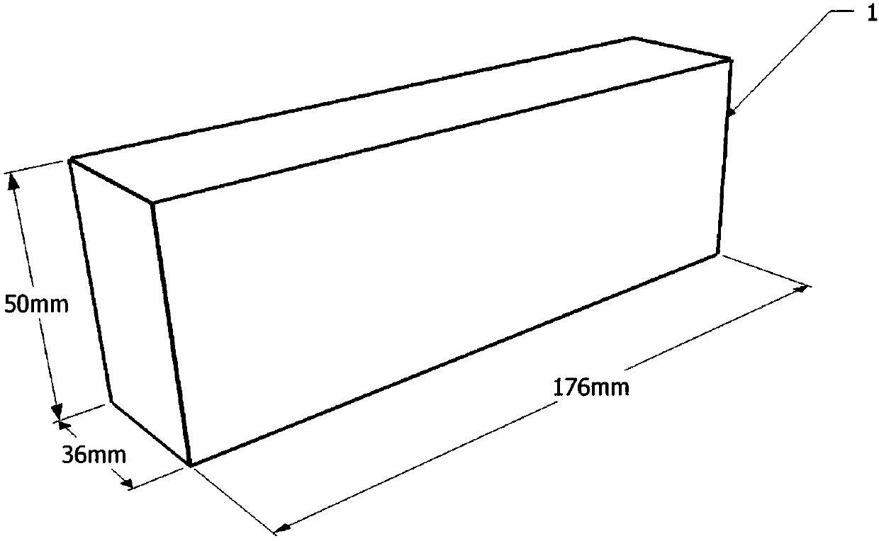
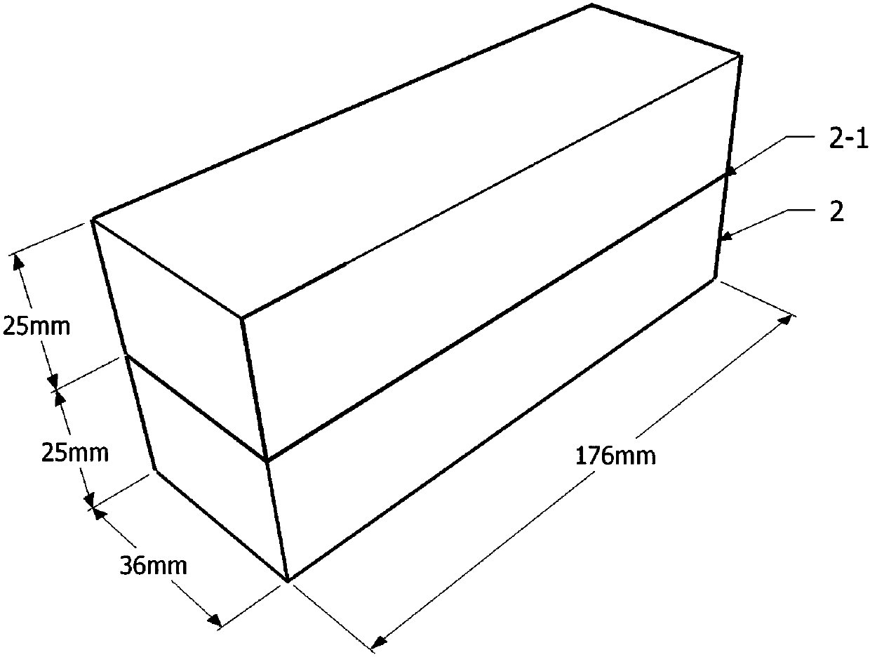
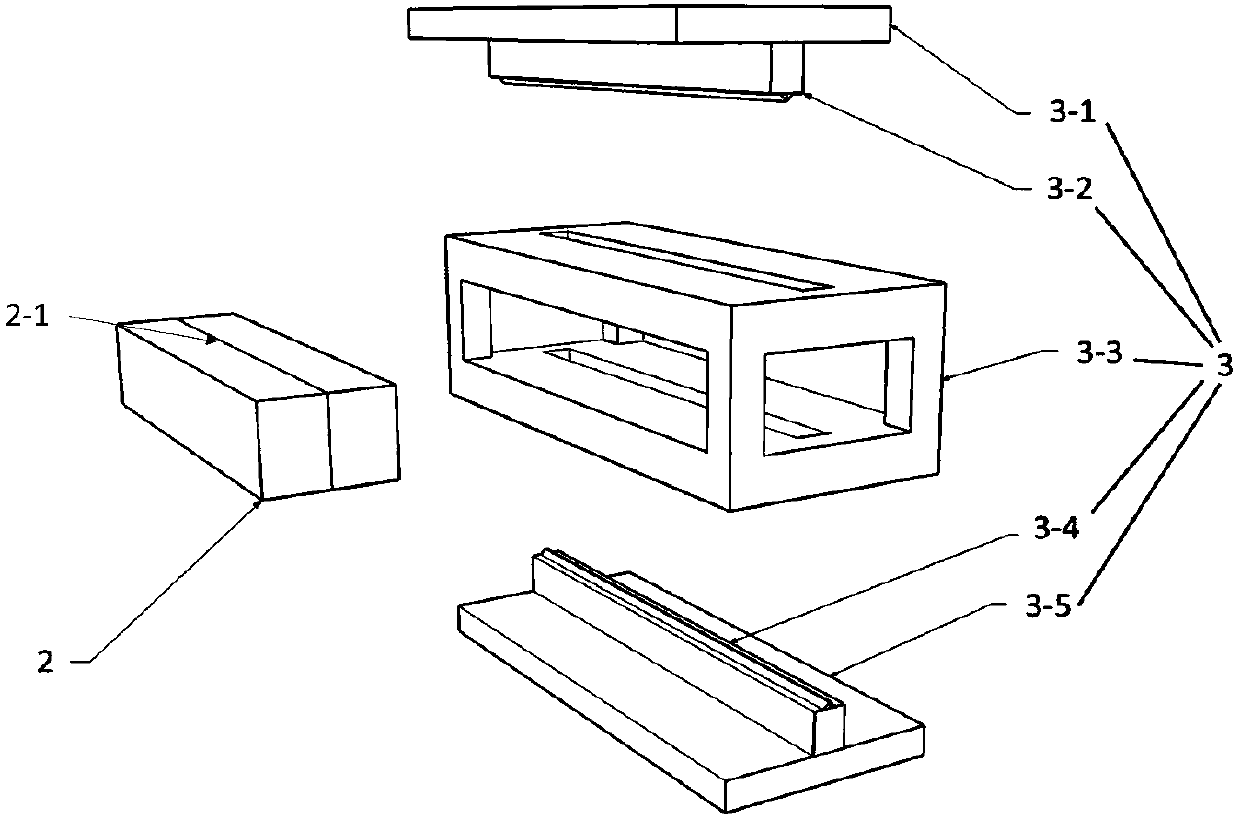
[0064] Make the original square rock slab 1 using the downhole core of the oil and gas reservoir section or outcrop rock in the same layer; prefabricate the scratch 2-1 in the middle of the original square rock slab 1; use the rock slab splitting device 3 to split the square rock with the prefabricated scratch Plate 2, and use a three-dimensional laser scanner to obtain the surface roughness morphology data of rock sample 4 after splitting; calculate the surface roughness coefficient JRC of rock sample 4 after splitting, and select a pair that best represents the reservoir according to the roughness coefficient JRC The split rock sample 4 of the hydraulic fracturing fracture surface morphology; the selected split ro...


PUM


Abstract

The invention discloses a manufacturing method for a manmade rock sample for simulating the real form of a hydraulic fracturing crack. An original square rock plate is manufactured through an underground rock core or same-layer-position outcrop rock of an oil gas reservoir section; the rock plate is split in the length direction through a rock plate splitting device, and a three-dimensional laserscanner is used for obtaining split rock sample surface rough feature data; the rock sample surface roughness coefficient after splitting is calculated, and a pair of split rock samples capable of most representing the reservoir hydraulic fracturing crack surface feature are selected according to the roughness coefficient; according to the surface roughness feature data, a 3D printer is used for manufacturing a manmade rock sample manufacturing die; manmade rock sample manufacturing materials are prepared according to reservoir section rock mineral components, and a manmade rock sample for simulating the real form of the hydraulic fracturing crack is formed through pressing. According to the manufacturing method, the principle is simple, adopted equipment facilitates machining and manufacturing, rock samples consistent to reservoir rock mineral in component and real and uniform in surface rough feature can be manufactured in batches, and testing is conveniently conducted.

Description

technical field [0001] The invention relates to the technical field of oil and gas production enhancement and reformation, in particular to a method for making artificial rock samples for simulating the real shape of hydraulic fracturing fractures. Background technique [0002] Hydraulic fracturing is the main measure for increasing production of oil and gas reservoirs. During construction, fracturing fluid with relatively high viscosity is squeezed into the oil and gas reservoir through the wellbore. When the injection rate of fracturing fluid exceeds the absorption capacity of the reservoir, it will High pressure is formed on the reservoir, and when this pressure exceeds the fracture pressure of the reservoir rock near the bottom of the well, the reservoir rock will be pushed apart and fractures will be generated. The rock is formed by the mutual bonding of various mineral particles and cement, and hydraulic fracturing fractures mainly extend along the part of the cement w...

Claims


Application Information

Patent Timeline
IPC IPC(8): E21B47/00E21B43/26G06Q50/02
CPCE21B47/00E21B43/26G06Q50/02
Inventor 陈迟赖杰郭建春黄楚淏黎俊峰段华
Owner SOUTHWEST PETROLEUM UNIV
Why Eureka
Try Eureka