Evaporation condensation device with high collection rate for preparing nano-metal

A nano metal, collection rate technology, applied in metal processing equipment, transportation and packaging, etc., can solve the problem that it is easy to fall on the outside of the funnel, and sometimes adhere to the inner wall of the vacuum chamber, reducing the practicability and equipment of the evaporation and condensation device. problems such as the reduction of collection efficiency, to achieve the effect of facilitating collection, improving practicability, and increasing collection rate

Inactive Publication Date: 2019-11-01
蒙正欢
View PDF0 Cites 2 Cited by
  • Summary
  • Abstract
  • Description
  • Claims
  • Application Information

AI Technical Summary

Problems solved by technology

[0003] It can be seen from the production process of evaporative condensation that in the process of collecting nanomaterials in the existing evaporative condensation device, it mainly relies on the scraper to scrape off the nanomaterials on the surface of the cooling rod. The self-material on the surface is scraped off, causing damage to the cooling rod, and when scraped off with a scraper, since the vacuum chamber is filled with inert gas, and the funnel at the bottom is still a certain distance from the cooling rod at the top of the vacuum chamber, the nano powder When the pellets fall down, they are easy to fall on the outside of the funnel, and sometimes they are attached to the inner wall of the vacuum chamber, which reduces the collection efficiency of the equipment, thereby reducing the practicability of the existing evaporative condensation device.

Method used


Image

  • Evaporation condensation device with high collection rate for preparing nano-metal
  • Evaporation condensation device with high collection rate for preparing nano-metal
  • Evaporation condensation device with high collection rate for preparing nano-metal

Examples


Embodiment Construction

[0024] The present invention is described in further detail now in conjunction with accompanying drawing. These drawings are all simplified schematic diagrams, which only illustrate the basic structure of the present invention in a schematic manner, so they only show the configurations related to the present invention.

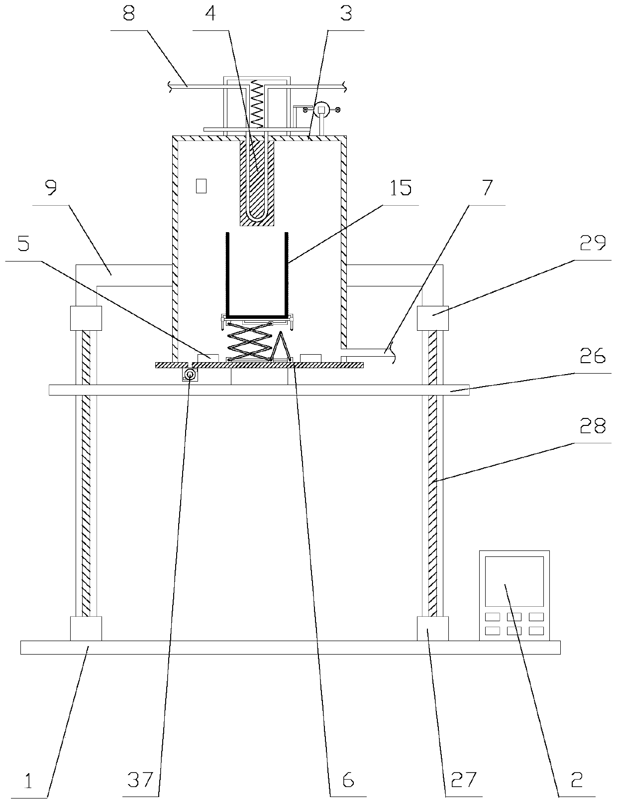
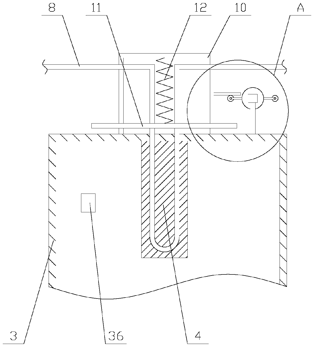
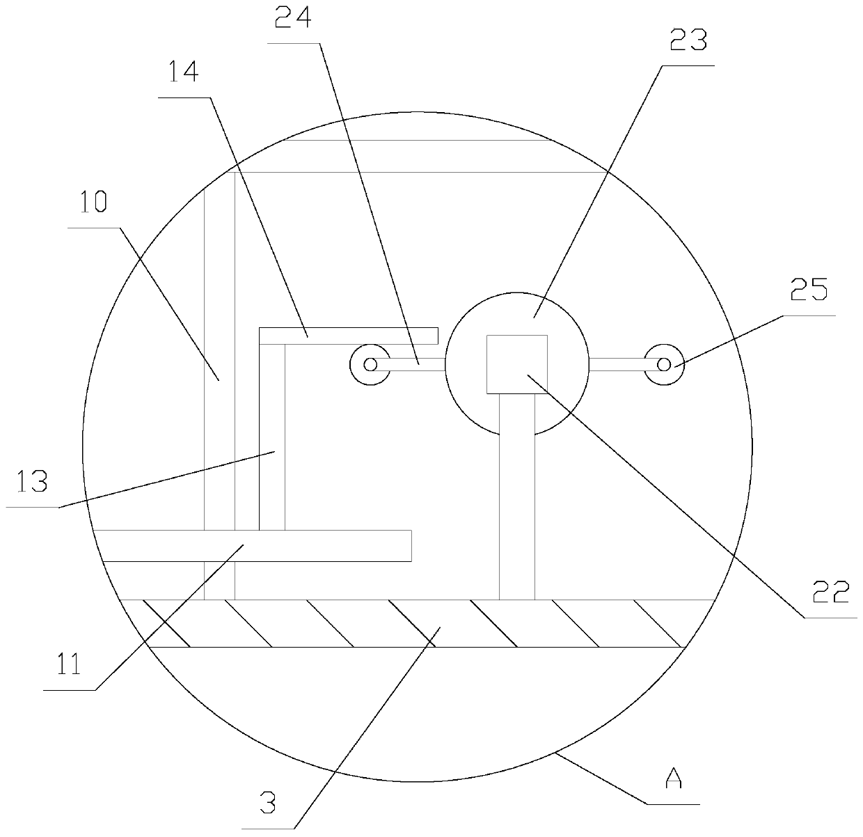
[0025] Such as figure 1 As shown, an evaporation condensation device with a high collection rate for preparing nanometer metals includes a base 1, a controller 2, a reaction chamber 3, a cooling rod 4, an evaporation source 5, a sealing plate 6, a vacuum pump 37, a gas delivery pipe 7, Lifting mechanism, liquid nitrogen tube 8, collecting mechanism, vibration mechanism and two legs 9, the controller 2 is fixed on the top of the base 1, the controller 2 is provided with a PLC, and the two legs 9 are respectively located in the reaction chamber 3 The two sides of the reaction chamber 3 are fixed above the base 1 through the feet 9, the sealing plate 6 is arrang...


PUM


Abstract

The invention relates to an evaporation condensation device with a high collection rate for preparing nano-metal. The evaporation condensation device comprises a base, a reaction chamber, a cooling rod, an evaporation source, a sealing plate, a lifting mechanism, a liquid nitrogen pipe, a collecting mechanism and a vibrating mechanism, wherein the vibrating mechanism comprises a support, a vibrating plate, a spring and a driving assembly, the driving assembly comprises a driving unit, a vertical plate and a transverse plate, and the collecting mechanism comprises a collecting box, a supportingplate, a supporting assembly and a mounting assembly. According to the evaporation condensation device with the high collection rate for preparing the nano-metal, after nano-metal powder particles are attached to the cooling rod, the collecting box is arranged on the cooling rod in a sleeve mode through the collecting mechanism, nano-metal material on the surface of the cooling rod is shaken offthrough the cooling rod and by virtue of the vibrating mechanism, the nano-metal material is prevented from falling to other positions in the reaction chamber, the nano-metal material falls in the collecting box in a centralized manner, so that the collection rate is improved, the cooling rod is prevented from being damaged, and meanwhile, the position of the collecting box is lowered through thelifting mechanism, so that the nano-metal material is conveniently collected, and the practicability of the device is improved.

Description

technical field [0001] The invention relates to the field of new material production equipment, in particular to an evaporation condensation device with high collection rate for preparing nanometer metals. Background technique [0002] Nano-metal materials are metals and alloys that form nano-grains. They have the characteristics of grain boundary ratio, specific surface energy, and surface atomic ratio. The particle size is reduced from 100nm to 5nm. Among the various methods of producing nano-metals, the evaporation and condensation method is a typical method of preparing nano-powders by physical methods. This method is to fill the vacuum evaporation chamber with a low-pressure inert gas, and through the heating of the evaporation source, the metal, alloy or compound to be prepared forms an ion body, collides with the inert gas atoms and loses energy, and then quenches it to condense it into nano-particles. After the powder particles and nano-metal particles accumulate on...

Claims


Application Information

Patent Timeline
IPC IPC(8): B22F9/06B22F1/00
CPCB22F9/06B22F1/054
Inventor 蒙正欢
Owner 蒙正欢
Why Eureka
Try Eureka