Ultrasonic main shaft and ultrasonic machine tool comprising same

An ultrasonic and spindle technology, applied to fluids that use vibration, metal processing machinery parts, metal processing equipment, etc., can solve problems such as instantaneous disconnection, low service life, damage to power plugs or power connectors, and achieve stable electrical conduction. , The effect of reducing the difficulty of alignment and avoiding leakage

Pending Publication Date: 2019-11-01
CONPROFE TECH GRP CO LTD +1
View PDF0 Cites 3 Cited by
  • Summary
  • Abstract
  • Description
  • Claims
  • Application Information

AI Technical Summary

Problems solved by technology

[0005] 1. There is an assembly gap between the inner and outer rings of the bearing and the steel ball. Therefore, when the inner ring and the steel ball rotate with the rotating shaft at high speed, the centrifugal force generated by it or the beating generated during cutting can easily make the inner ring and the steel ball separate. Contact, and then the situation of instantaneous disconnection occurs, so that the tool cannot stably vibrate at high frequency, which affects the cutting operation effect of high frequency vibration
[0006] 2. For the carbon brush structure, due to the technical means of the existing elastic carbon brush parts, the elastic parts provide the elastic force to push each of the carbon brush parts to move in the direction of the main shaft. If the compression amount of the elastic parts is too large, its The pushing elastic force will also be relatively increased, which will cause more serious wear of the carbon brush parts; on the contrary, if the compression of the elastic part is too small, the pushing elastic force will be insufficient, and the carbon brush parts will not be able to contact Conductive ring, even in the event of an open circuit
[0007] 3. When the insertion part of the ultrasonic handle has not been fully inserted into the sleeve and positioned in the sleeve hole of the rotating shaft, since the ultrasonic handle still has a positional deviation from the rotating shaft, relatively, the power plug of the ultrasonic handle The first and second electrodes and the first and second conductive elements of the power connector have not yet been accurately aligned. Therefore, when the first and second electrodes of the power plug are first inserted into the first and second conductive elements of the power connector, it is easy to cause Damage to the power plug or power connector
[0008] 4. Since the shapes of the second conductive element of the power connector and the second electrode of the power plug are quite tapered, during the insertion process of the second electrode of the power plug and the second conductive element of the power connector, The two must be aligned more precisely. If the position is slightly deviated, the second electrode or the second conductive element is easily damaged due to abrasion or bending
[0009] To sum up, the conductive structure of the existing ultrasonic spindle not only has a low service life, but also makes it impossible for the power supply to stably transmit electric energy to the oscillator of the knife handle, and the cutting effect is poor

Method used


Image

  • Ultrasonic main shaft and ultrasonic machine tool comprising same
  • Ultrasonic main shaft and ultrasonic machine tool comprising same
  • Ultrasonic main shaft and ultrasonic machine tool comprising same

Examples


Embodiment 1

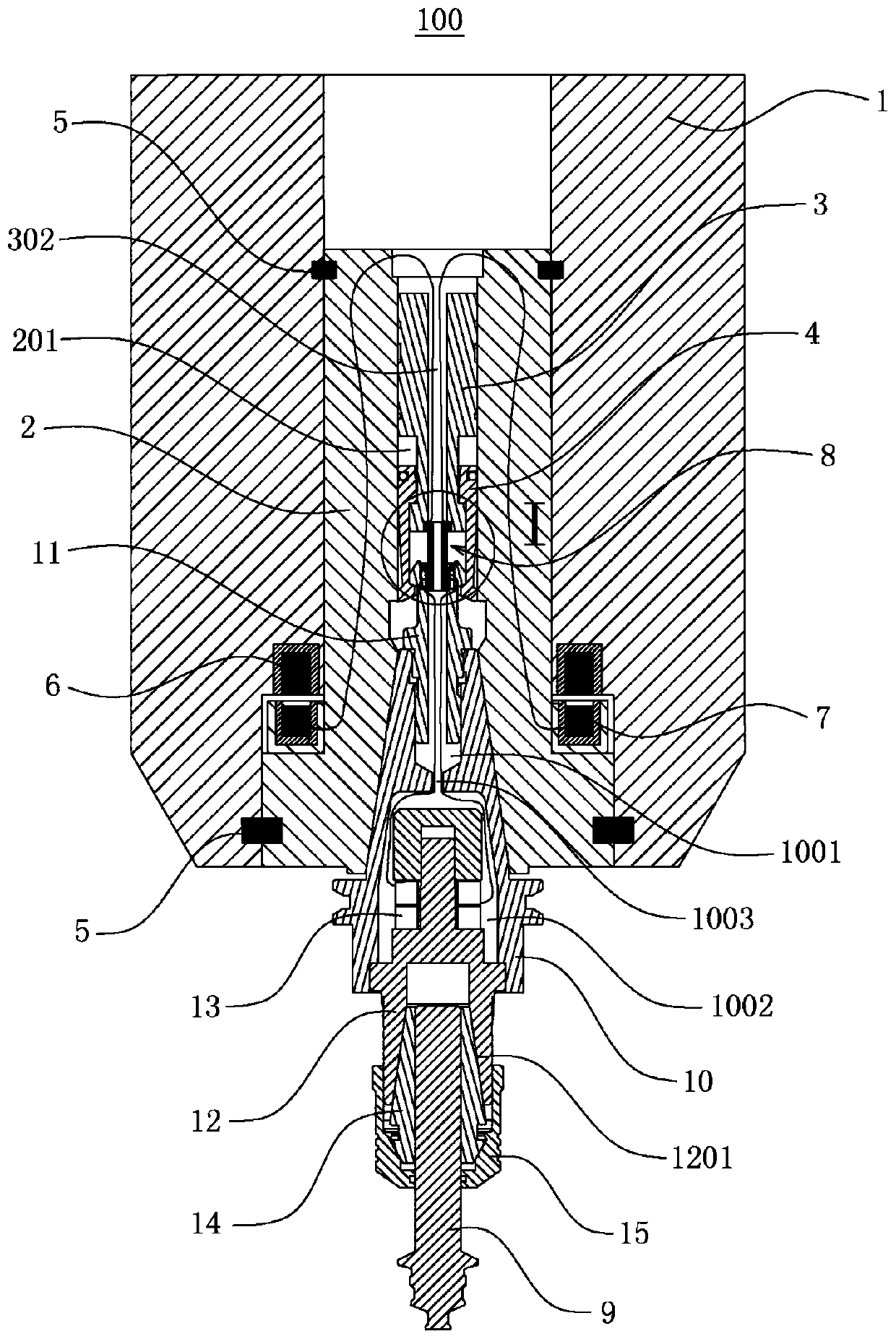
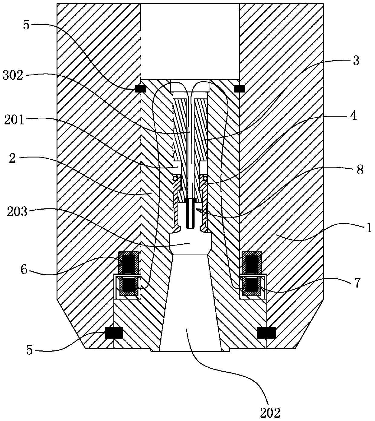
[0055] Such as figure 1 As shown, the embodiment of the present invention provides an ultrasonic spindle 100, which mainly includes a cylinder seat 1, a rotating shaft 2, a pull rod 3, a clamping jaw 4 and an ultrasonic processing assembly.

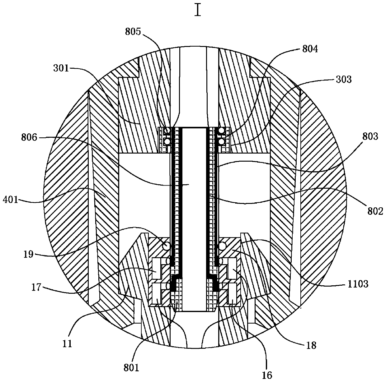
[0056] Specifically, such as Figure 1 to Figure 3 As shown, the cylinder base 1 is a fixed part, and the rotating shaft 2 passes through the cylinder base 1 and is connected with the cylinder base 1 through a bearing 5, so that the rotating shaft 2 can rotate relative to the cylinder base 1 . A cavity 201 is provided inside the rotating shaft 2 , and the pull rod 3 is disposed in the cavity 201 and can slide up and down along the cavity 201 . The front end of the pull rod 3 is provided with a claw seat 301 , the jaw 4 is connected with the pull rod 3 through the claw seat 301 , and can slide up and down along with the pull rod 3 . The front end of the rotating shaft 2 is provided with a sleeve hole 202 communicating with the cavity 201...

Embodiment 2

[0073] Such as Figure 5 As shown, the embodiment of the present invention provides an ultrasonic machine tool, which mainly includes an ultrasonic power supply 200 and the ultrasonic main shaft 100 provided in Embodiment 1, wherein the wireless transmitting component 6 of the ultrasonic main shaft 100 is electrically connected to the ultrasonic power supply 200, and the ultrasonic power supply 200 It can be an external power supply independent of the ultrasonic machine tool, or it can be integrated on the ultrasonic machine tool.

[0074] To sum up, the embodiment of the present invention provides an ultrasonic spindle 100 and an ultrasonic machine tool including it. Compared with the prior art, the ultrasonic spindle 100 has a long service life, stable electrical conduction, can meet the requirements of high speed, and is safe. High performance, good processing effect, etc., because the ultrasonic machine tool adopts the above-mentioned ultrasonic spindle 100, it also has th...


PUM


Abstract

The invention relates to the technical field of ultrasonic processing and discloses an ultrasonic main shaft, which is characterized in that on one hand, a wireless transmitting assembly and a wireless receiving assembly are arranged on the ultrasonic main shaft, and non-contact type electrical conduction is formed between a rotating shaft and a cylinder seat, so that the abrasion of a conductivestructure can be avoided, the service life of the main shaft is prolonged, and the cutting operation effect of high-frequency vibration is improved; and on the other hand, since conductive pieces areall concentrated on a rod body, the double para-position is converted into a single para-position, which greatly reduces the difficulty of the alignment, therefore, in the process of sleeving an ultrasonic knife handle and a rotating shaft, only the rod body is butted with a blind rivet, the conductive pieces and a conductive body can form effective electric connection, and furthermore, stable electrical conduction can be formed between the ultrasonic knife handle and the rotating shaft, and no contact failure occurs. In addition, the invention also provides an ultrasonic machine tool which also has the advantages of stable electrical conduction, good processing effect and the like.

Description

technical field [0001] The invention relates to the technical field of ultrasonic processing, in particular to an ultrasonic spindle and an ultrasonic machine tool including the same. Background technique [0002] Introducing a high-frequency vibration machining mechanism in the process of machining operations can not only improve the surface roughness of the cutting surface and improve machining accuracy, but also reduce cutting resistance and increase the life of the tool, so it is gradually widely used. [0003] The existing ultrasonic spindle is usually composed of a base, a rotating shaft and an ultrasonic handle. The bearings or carbon brushes between the bodies form an electrical connection with an external power source. The power connector is provided with a first conductive element in the shape of a thick tube, and a second conductive element in the shape of a thin tube is insulated in the first conductive element. The ultrasonic tool handle is equipped with a con...

Claims


Application Information

Patent Timeline
Patent Type & Authority Applications(China)
IPC IPC(8): B23B19/02B06B1/02
CPCB06B1/02B23Q1/70
Inventor 颜炳姜李伟秋
Owner CONPROFE TECH GRP CO LTD
Why Eureka
Try Eureka