Pipeline hydroelectric generating set

A technology for generators and pipelines, applied in hydroelectric power generation, electric components, engine components, etc., which can solve problems such as low power generation efficiency and small force

Pending Publication Date: 2019-11-01
陈向阳
View PDF1 Cites 1 Cited by
  • Summary
  • Abstract
  • Description
  • Claims
  • Application Information

AI Technical Summary

Problems solved by technology

[0003] There are several pipeline hydroelectric generators at present, such as the pipeline hydroelectric generator wi

Method used


Image

  • Pipeline hydroelectric generating set
  • Pipeline hydroelectric generating set
  • Pipeline hydroelectric generating set

Examples


Embodiment 1

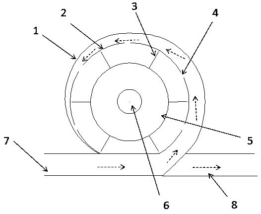
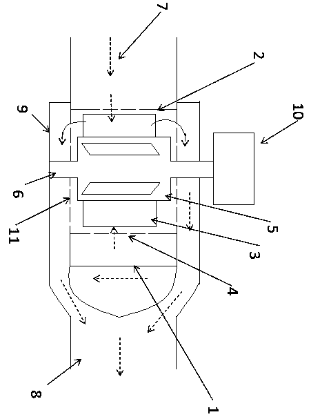
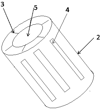
[0025] During specific use, the water inlet pipe 7 is connected with the external water delivery pipe, and the water flow enters the gap between the sealed casing 1 and the casing 2 in the pipeline hydroelectric generator 10 group through the water inlet pipe 7, and passes through the top of the casing 2. The water spray port 4 opened enters the inside of the housing 2, and impacts the blade 3 on the hydraulic rotating device arranged inside the housing 2, drives the blade 3 to rotate, drives the rotation shaft 5 fixedly connected with the blade 3 to rotate through the blade 3, and Driven by the rotary shaft 5 and rotated by the power output shaft 6 to drive the generator 10 to generate electricity.

[0026] After the water enters the gap between the sealed shell 1 and the shell 2, it flows along the gap, and after encountering the water spray port 4 on the shell 2, it will enter the hydraulic rotating device along the water spray port 4, and the sealed shell The gap between 1...


PUM


Abstract

The invention discloses a pipeline hydroelectric generating set which comprises a generator and a hydraulic rotating device. The hydraulic rotating device comprises a sealing shell and a rotating assembly, and the rotating assembly is located at the central position of the sealing shell; the rotating assembly comprises a housing, a rotating shaft and a plurality of blades disposed on the rotatingshaft, a water inlet pipeline and a water outlet are formed in the sealing shell, the water inlet pipeline is disposed on one side of the sealing shell and penetrates through the sealing shell, and the water inlet pipeline is inserted into a gap between the sealing shell and the housing; and a plurality of water spraying openings are formed in the housing so as to enable water flow in the gap between the housing and the sealing shell to enter the housing and to impact the blades to rotate to drive the generator connected to the rotating shaft to generate electricity. The water flow in the pipeline is directly in contact with the rotating blades, and the kinetic energy of the water flow drives the blades to rotate to generate electricity, that is, the water flow speed is reduced, and the kinetic energy of the water flow is converted into electrical energy to be stored, so that the energy utilization efficiency is improved; and the rotating shaft is arranged perpendicular to the pipeline, the contact area between the water flow and the blades is large, the acting force is large, and the electricity generation effect is good.

Description

technical field [0001] The invention relates to a hydropower generating device, in particular to a pipeline hydropower generating set. Background technique [0002] The current development in the field of clean energy has involved many fields, including the use of solar energy, wind energy, hydropower and tidal energy. my country's investment in hydraulic power also accounts for a large proportion. The known hydroelectric power generation mostly uses the height difference of the water flow to drive the generator set to run and generate electricity. These are mostly used in large-scale hydraulic engineering offices, but there are many other hydraulic powers that have not been utilized in daily life. When the water in the pipeline is going from one place to another, the kinetic energy generated by the water flow will gradually increase, and the pressure at the water outlet will be high, affecting normal use, and even need to install a pressure reducing valve at the water outl...

Claims


Application Information

Patent Timeline
IPC IPC(8): F03B13/00F03B1/04F03B1/02F03B11/02H02K7/18
CPCF03B1/02F03B1/04F03B11/02F03B13/00H02K7/1823Y02E10/20
Inventor 陈向阳陈怡冰
Owner 陈向阳
Why Eureka
Try Eureka