Magnetoelectric dipole filter antenna with approximate elliptical filter response

A filter response, approximate ellipse technology, applied to antennas, resonant antennas, antenna grounding devices, etc., can solve problems such as affecting the antenna radiation pattern, increasing the complexity of the feed network, and deteriorating the radiation pattern, achieving stable gain and symmetry pattern, improved out-of-band radiation suppression level, and the effect of good filtering frequency response

Active Publication Date: 2019-11-01
XIDIAN UNIV
View PDF6 Cites 16 Cited by
  • Summary
  • Abstract
  • Description
  • Claims
  • Application Information

AI Technical Summary

Problems solved by technology

[0004] (1) In the existing filter antenna designed based on the principle of filter synthesis, the multi-order resonator in the filter introduces a large insertion loss and reduces the gain of the antenna; by introducing a resonant structure into the antenna radiator or feed network, the feed The complexity of the electrical network affects the radiation pattern of the antenna.
[0005] (2) The cross-coupling design method, due to the need to create a cross-coupling path, is only applicable to a specific antenna form, and its scope of application is limited
[0006] (3) For filter antennas designed based on the principle of radiation cancellation, the radiation pattern may deteriorate
[0007] (4) The bandwidth of the existing filter antenna is not wide enough to meet the broadband requirements of modern wireless communication
[0008] The difficulty of solving the above technical problems: to solve the problem of large insertion loss and reduce the antenna gain, the key is not to introduce multi-order filters under the premise of realizing the filter response; to solve the problem of narrow bandwidth, the key is to choose the antenna form with wide bandwidth to realize the filter antenna

Method used


Image

  • Magnetoelectric dipole filter antenna with approximate elliptical filter response
  • Magnetoelectric dipole filter antenna with approximate elliptical filter response
  • Magnetoelectric dipole filter antenna with approximate elliptical filter response

Examples


Embodiment Construction

[0036] In order to make the object, technical solution and advantages of the present invention more clear, the present invention will be further described in detail below in conjunction with the examples. It should be understood that the specific embodiments described here are only used to explain the present invention, not to limit the present invention.

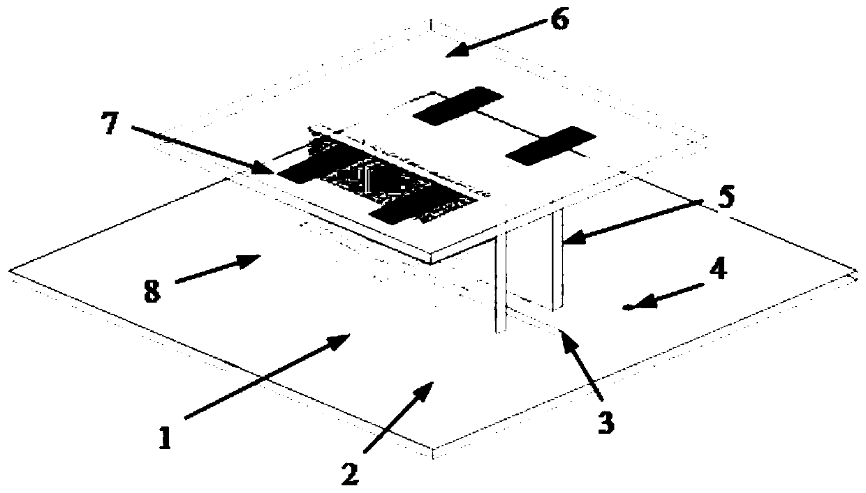
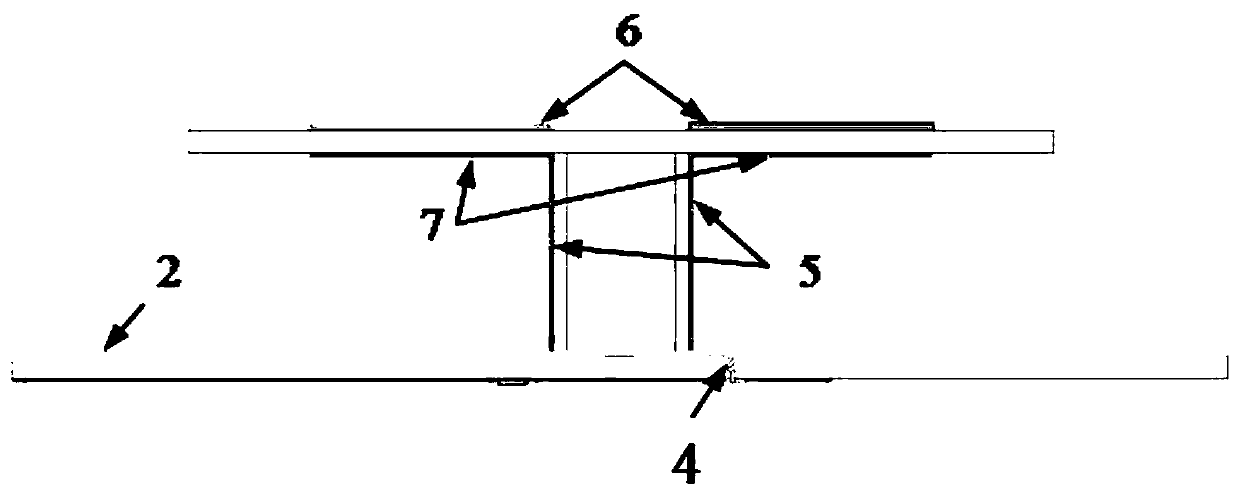
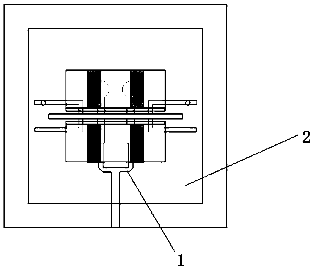
[0037] For the existing filter antenna, the bandwidth is not wide enough to meet the technical problem of modern wireless communication's requirement for broadband. The present invention utilizes the inherent radiation zero point of the magnetoelectric dipole antenna at the low-frequency edge of the passband, and then introduces a coupling stub and a U-shaped short-circuit stub to realize a radiation zero point at the high-frequency edge of the passband and the low-frequency stopband respectively, thereby realizing an approximate Magnetoelectric Dipole Filter Antenna with Elliptical Filter Response.

[0038] The technical ...


PUM


Abstract

The invention belongs to the technical field of wireless communication, and discloses a magnetoelectric dipole filter antenna with an approximate elliptical filter response. A feed structure comprisesa coupling groove printed on the upper layer of a double-sided copper-clad dielectric plate, and a fork-shaped microstrip power divider and a U-shaped short circuit branch printed on the lower layerof a double-sided copper-clad dielectric plate with a thickness of 1 mm; the radiation structure includes a radiation patch, a coupling branch, and a vertical short circuit wall; the radiation patch and the coupling branch are respectively printed on the upper layer and the lower layer of a double-sided copper-clad dielectric plate with a thickness of 1.5 mm; and the vertical short circuit wall isprinted on two one-sided copper-clad dielectric plates with a thickness of 0.5 mm. The magnetoelectric dipole filter antenna with an approximate elliptical filter response is realized, and a good filter frequency response is realized. The magnetoelectric dipole filter antenna with the approximate elliptical filter response disclosed the invention greatly expands the application of the magnetoelectric dipole antenna in the field of filter antennas.

Description

technical field [0001] The invention belongs to the technical field of wireless communication, in particular to a magnetoelectric dipole filter antenna with approximately ellipse filter response. Background technique [0002] At present, the closest prior art: the methods for implementing filter antennas in the industry mainly include the following: first, an antenna radiator is used to replace the last-order resonator of a bandpass filter to implement a filter antenna. Based on the principle of filter synthesis, the bandpass filter needs to be designed in advance. Although this method can achieve a good filter response, the insertion loss introduced by the multi-order resonator in the bandpass filter reduces the radiation gain of the antenna. In order to solve this problem, a design method of a filter antenna without using an additional filter circuit is proposed. It includes two aspects, on the one hand, introducing a resonant structure in the antenna feed network, and o...

Claims


Application Information

Patent Timeline
Patent Type & Authority Applications(China)
IPC IPC(8): H01Q1/38H01Q1/50H01Q1/48H01Q15/00H01Q9/16
CPCH01Q1/38H01Q1/48H01Q1/50H01Q9/16H01Q15/0053
Inventor 任建隗兆辉尹应增
Owner XIDIAN UNIV
Why Eureka
Try Eureka