

High voltage piezoelectric ceramic driving power source and control method thereof
A piezoelectric ceramic drive and power supply technology, which is applied in the direction of piezoelectric effect/electrostrictive or magnetostrictive motors, generators/motors, electrical components, etc., can solve problems that cannot meet high voltage and high current requirements Problems such as piezoelectric ceramics, output current ripple cannot be guaranteed, and the circuit of the series half-bridge circuit are complicated, etc., to achieve the effect of increasing power, simple circuit, and easy integration
- Summary
- Abstract
- Description
- Claims
- Application Information
AI Technical Summary
Problems solved by technology
Method used
Image

Examples
Embodiment 1
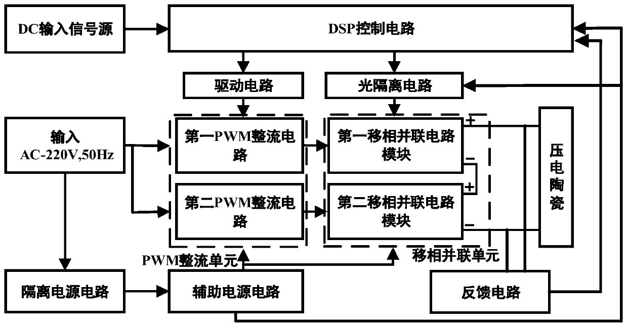
[0034] Such as figure 1As shown, in Embodiment 1, a high-voltage piezoelectric ceramic drive power supply specifically includes a phase-shifting parallel circuit unit, a DSP control circuit, a PWM rectifier circuit unit, an optical isolation unit, a drive circuit, a feedback circuit, and an isolated power supply circuit and auxiliary power circuits. The PWM rectifier circuit unit performs AC-DC rectification on the AC220V mains power, and outputs a stable DC voltage of 380-500V to the phase-shifting parallel circuit unit, and the stable DC voltage of 380-500V is used as the input DC voltage signal of the phase-shifting parallel circuit unit; The DSP control circuit receives an external DC signal source, analyzes the output voltage amplitude and frequency, and generates a SPWM signal with the first phase difference according to the number of half-bridge inverter circuits in the phase-shifting parallel circuit unit, and controls the phase-shifting parallel circuit through the op...
Embodiment 2
[0042] This implementation provides a control method for a high-voltage piezoelectric ceramic drive power supply on the basis of Embodiment 1, which has the same inventive concept as Embodiment 1, and the method specifically includes:
[0043] S01: The phase-shifting parallel circuit unit adjusts the amplitude and frequency of the output signal according to the SPWM signal and the DC signal. Wherein, the SPWM signal is an SPWM signal with a first phase difference, and the first phase difference is determined according to the number of half-bridge inverter circuits in the phase-shifting parallel circuit unit, which is used to ensure that the phase-shifting parallel circuit unit can output a continuously adjustable frequency-amplitude-modulated sine wave wave voltage signal.
[0044] Further, adjusting the amplitude and frequency of the output signal includes:
[0045] S02: Adjust the SPWM fundamental wave frequency to realize the adjustment of the output current frequency of t...
PUM
 Abstract
Description
Claims
Application Information