Grinding device and grinding method for spiral blade for machining pump

A technology for helical blades and pumps, which is applied in the field of grinding devices for processing helical blades of pumps, can solve the problems of low processing efficiency, inability to grind parts, and high cost of construction, so as to improve grinding accuracy and grinding efficiency, increase service life, Improve the effect of grinding precision

Active Publication Date: 2019-11-05
肇庆全球泵业有限公司
View PDF12 Cites 0 Cited by
  • Summary
  • Abstract
  • Description
  • Claims
  • Application Information

AI Technical Summary

Problems solved by technology

[0003] However, the existing grinding machines and the grinding machines have the following problems: (1) the cost of the current grinding machines is too high, and most of them are processed by semi-automatic grinding machines; The steps are too cumbersome, and the processing efficiency and economic benefits are low; (3) At present, the grinding process of the spiral line can be realized, but for the processing of the spiral parts, it is still manually polished slowly. The conventional grinding machine fixes the part, or fixes one end of the part but can only move in one direction, and cannot grind the part from multiple angles and directions, resulting in the inability to effectively process the spiral blade, and there is no automatic grinding machine on the market. Machining of spiral blades
[0004] To sum up, the above-mentioned grinding machines have the problems of high cost, cumbersome processing, low processing efficiency and inability to automatically process spiral parts

Method used


Image

  • Grinding device and grinding method for spiral blade for machining pump
  • Grinding device and grinding method for spiral blade for machining pump
  • Grinding device and grinding method for spiral blade for machining pump

Examples


Embodiment Construction

[0025] The following will clearly and completely describe the technical solutions in the embodiments of the present invention with reference to the accompanying drawings in the embodiments of the present invention. Obviously, the described embodiments are only some, not all, embodiments of the present invention.

[0026] In describing the present invention, it should be understood that the terms "upper", "lower", "front", "rear", "left", "right", "top", "bottom", "inner", " The orientation or positional relationship indicated by "outside" and so on is based on the orientation or positional relationship in the drawings, which is only for the convenience of describing the present invention and simplifying the description, rather than indicating or implying that the device or element referred to must have a specific orientation or a specific orientation. construction, operation, and therefore should not be construed as limiting the invention.

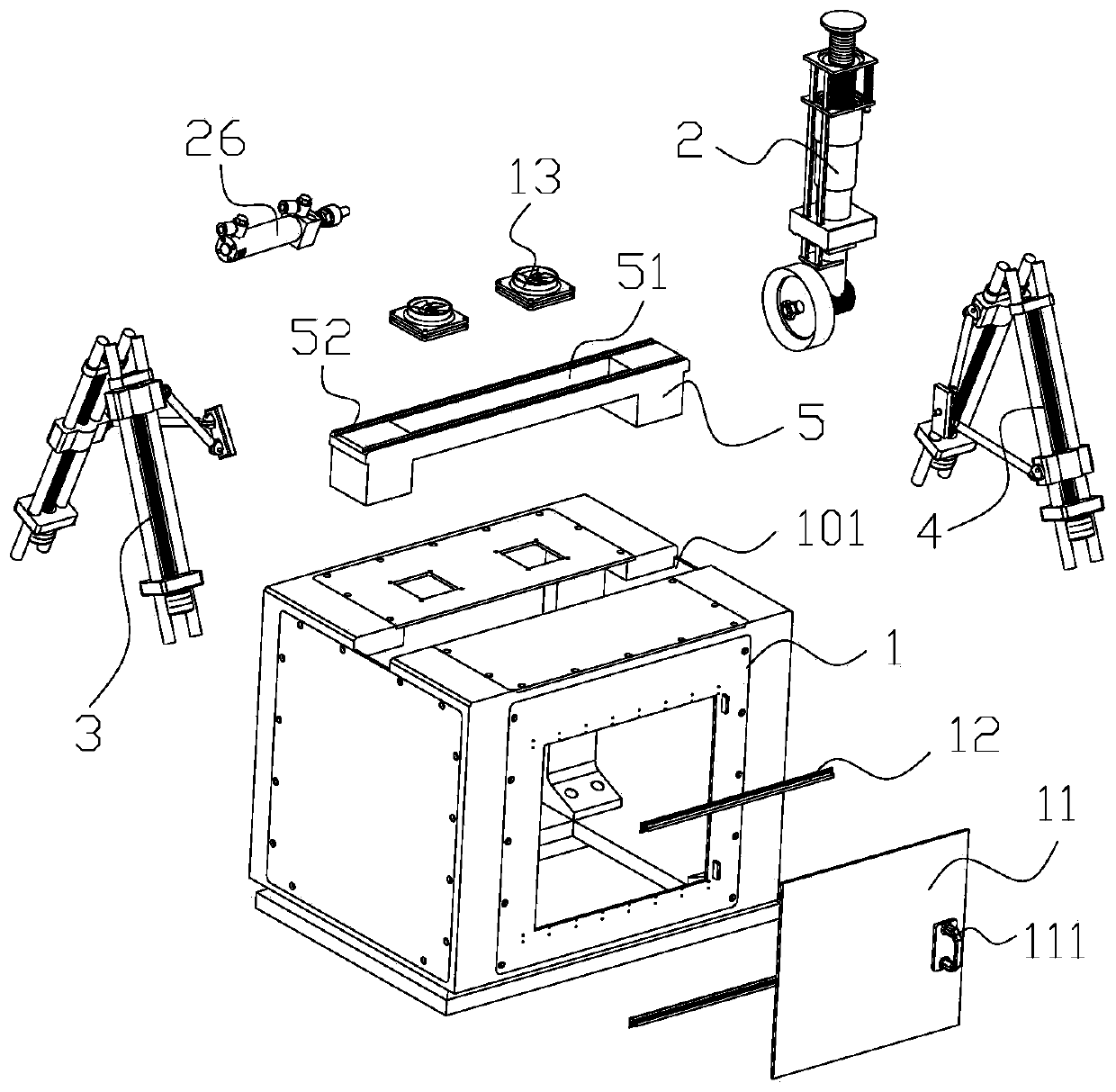
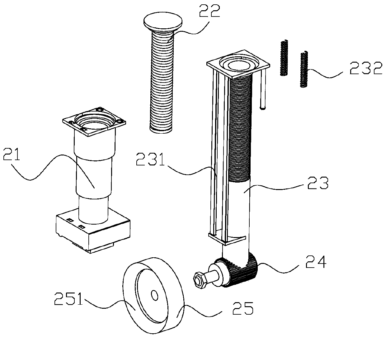
[0027] Such as figure 2 As shown ...


PUM


Abstract

The invention relates to the technical field of machining. The invention discloses a grinding device for a spiral blade for a machining pump. The grinding device for the spiral blade for the machiningpump comprises a case, a grinding assembly, a first rotary drive assembly and a second rotary drive assembly, a neutral gear is arranged in the middle of the top surface of the case, and a slide railis arranged on the neutral gear; a slide rail neutral gear is arranged the middle of the slide rail, the grinding assembly is matched with the slide rail, the first rotary drive assembly and the second rotary drive assembly are arranged on the left side and the right side of the case, the lower end of the first rotary drive assembly is arranged on the case, the upper end of the first rotary driveassembly is arranged on the slide rail, a part is fixed between the first rotary drive assembly and the second rotary drive assembly, and the part is polished into a spiral shape through the grindingassembly matched with the first rotary drive assembly and the second rotary drive assembly. The grinding device and grinding method have the technical effects that the cost of the device is low, thestructure is ingenious, the operation is convenient and rapid, the machining efficiency is high, and the automatic machining of the spiral blade is realized.

Description

technical field [0001] The invention relates to the technical field of mechanical processing, in particular to a grinding device and a grinding method for processing spiral blades for pumps. Background technique [0002] In actual production, modern CNC grinding machine equipment has realized automatic spiral processing, such as a fully automatic complex spiral grinding machine disclosed in the Chinese utility model patent with the publication number CN207402227U and the announcement date of 2018.05.25, including the bed , a grinding head assembly equipped with a grinding wheel, a head frame assembly equipped with a workpiece fixture, a dresser assembly equipped with a dressing wheel, and a feeding assembly; the bottom of the grinding head assembly and the head frame assembly are respectively installed with mutually perpendicular X-axis servo drives Linear sliding unit 1 and Z-axis servo-driven linear sliding unit 2. Pneumatic linear sliding unit 3 parallel to the Z-axis is ...

Claims


Application Information

Patent Timeline
Patent Type & Authority Applications(China)
IPC IPC(8): B24B19/14B24B41/06B24B47/12B24B47/20
CPCB24B19/14B24B41/06B24B47/12B24B47/20
Inventor 张美华邵权钰周振云
Owner 肇庆全球泵业有限公司
Why Eureka
Try Eureka