Z-shaped dual-clamp-plate joint assembly type H-shaped steel beam square steel tube column steel structure system

A prefabricated, double plywood technology, which is applied to floors, building components, building structures, etc., can solve problems such as the inability to guarantee the connection performance between the floor slab and the steel beam, the difficulty in guaranteeing the relative position construction accuracy, and the unfavorable operation of the assembled steel beam, etc. Achieve the effect of reducing on-site construction operations, ensuring connection performance, and improving construction accuracy

Pending Publication Date: 2019-11-05
北京国电恒嘉科技产业集团有限公司
View PDF0 Cites 6 Cited by
  • Summary
  • Abstract
  • Description
  • Claims
  • Application Information

AI Technical Summary

Problems solved by technology

[0003] In the existing technology, the prefabricated buildings are assembled by a large number of on-site welding work on the steel structure, which is not conducive to the improvement of production efficiency, and the steel structures are spliced ​​with each other during the on-site construction process, and the relative position construction accuracy is difficult to guarantee. It is beneficial to the later work of assembling steel beams on site, and it is time-consuming and labor-intensive
In addition, most of the existing technologies use profiled steel composite floors, reinforced concrete floors or OSB particle boards, which require a lot of on-site construction work and cannot guarantee the connection performance between the floors and steel beams

Method used


Image

  • Z-shaped dual-clamp-plate joint assembly type H-shaped steel beam square steel tube column steel structure system
  • Z-shaped dual-clamp-plate joint assembly type H-shaped steel beam square steel tube column steel structure system
  • Z-shaped dual-clamp-plate joint assembly type H-shaped steel beam square steel tube column steel structure system

Examples


Embodiment Construction

[0031] In order to make the purpose, technical solutions and advantages of the embodiments of the present invention clearer, the technical solutions in the embodiments of the present invention will be clearly and completely described below in conjunction with the drawings in the embodiments of the present invention. Obviously, the described embodiments It is a part of embodiments of the present invention, but not all embodiments. Based on the embodiments of the present invention, all other embodiments obtained by persons of ordinary skill in the art without making creative efforts belong to the protection scope of the present invention.

[0032] Below in conjunction with accompanying drawing, the present invention is described in further detail:

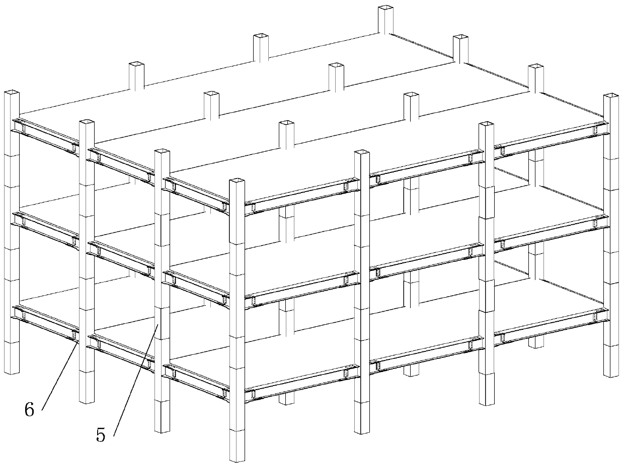
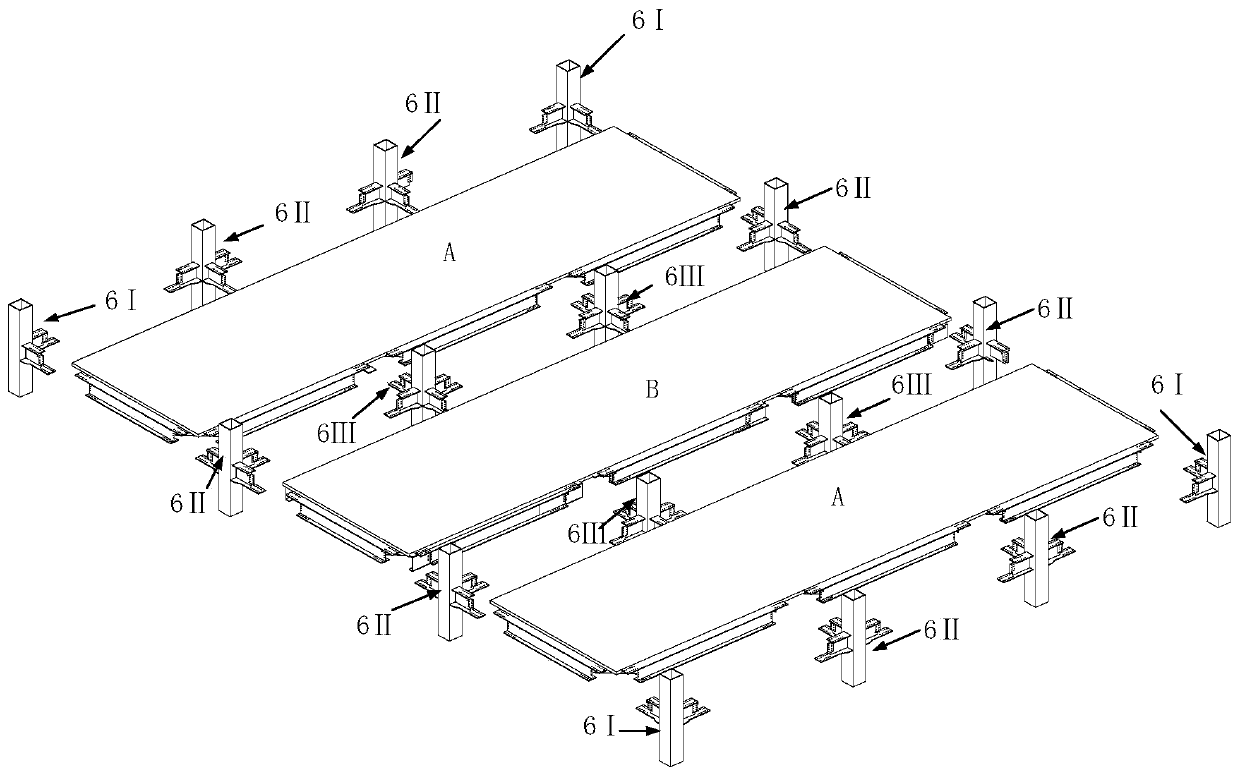
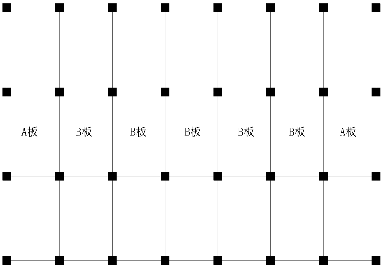
[0033] Such as Figure 1 to Figure 3 As shown, a Z-shaped double plywood joint assembled H-shaped steel beam square steel pipe column steel structure system provided by the present invention includes: assembled laminated beam-slab a...


PUM


Abstract

The invention discloses a Z-shaped dual-clamp-plate joint assembly type H-shaped steel beam square steel tube column steel structure system. The Z-shaped dual-clamp-plate joint assembly type H-shapedsteel beam square steel tube column steel structure system comprises assembly type superposed beam plates and an assembly type beam column joint; the assembly type superposed beam plates are in assembled connection through the assembly type beam column joint, the assembly type beam column joint comprises a box-shaped column, a joint connecting part and a joint rib plate, the joint connecting partis an I-shaped section steel beam with one end flat and the other end cut, a precast concrete plank is mounted in a corresponding steel frame structure, a factory-made concrete layer is formed throughpouring on the precast concrete plank in a factory, and a cast-in-place concrete layer is formed through pouring on the factory-made concrete layer in the site construction process. Through the technical scheme, the steel structure site welding work is greatly reduced, the factory prefabricated modular structure can greatly improve the construction precision, work efficiency is improved, the construction proceed is improved, and meanwhile, the connecting property of the floor and the steel beam can be ensured.

Description

technical field [0001] The invention relates to the technical field of structural engineering, in particular to an assembled H-shaped steel beam square steel pipe column steel structure system with Z-shaped double plywood joints. Background technique [0002] Prefabricated buildings are the focus of development in the construction industry for a period of time in the future, and the innovation of industrialized prefabricated structural systems is imperative. The prefabricated structural system refers to the building produced by making housing units or components according to uniform and standard building part specifications, and then transporting them to the construction site for assembly in place. A large number of building parts are produced and processed by the workshop, a large number of assembly operations on site, standardization of design and informatization of management meet the requirements of green buildings. It is characterized by light building weight, energy s...

Claims


Application Information

Patent Timeline
IPC IPC(8): E04B1/24E04B1/58E04B5/38
CPCE04B1/2403E04B5/38E04B2001/2406E04B2001/2418E04B2001/2415
Inventor 唐嘉临马骏
Owner 北京国电恒嘉科技产业集团有限公司
Why Eureka
Try Eureka