Novel tunneling process

A technology for excavating working face and process, which is applied in mining equipment, earth-moving drilling, pillars/supports, etc., can solve problems such as the speed of tunnel excavation can not keep up, restrict coal mining output of coal mines, hinder the progress of excavation work, etc. Conducive to safety management, convenient operating environment, limiting and preventing deformation and damage of surrounding rock

Active Publication Date: 2019-11-05
SHENYANG TIAN AN TECH CO LTD
View PDF5 Cites 5 Cited by
  • Summary
  • Abstract
  • Description
  • Claims
  • Application Information

AI Technical Summary

Problems solved by technology

However, the substantial increase in the output of the working face is accompanied by the consumption of a large number of mining roadways, which leads to the problem that the speed of roadway excavation operations cannot keep up with the needs of mining operations, which seriously restricts the improvement of the overall coal mining output of the coal mine.
At present, the commonly used roadway excavation process is: coal cutting and coal removal—temporary support—side cleaning—permanent support; that is, the roadheader excavates a certain distance, then exits, and then manually, bolter or bolter Anchor mesh operation, this traditional excavation process, after the excavation machine is cut, most of the time the operator relies on manual or bolter drilling machine to drill the anchor hole, surf the net, and drive the anchor when the excavator is stopped. Waiting for support operations, so that the tunneling efficiency of the roadheader can only be exerted by 20% to 25%, and the work efficiency is very low, which hinders the progress of the tunneling work

Method used


Image

  • Novel tunneling process
  • Novel tunneling process
  • Novel tunneling process

Examples


Embodiment Construction

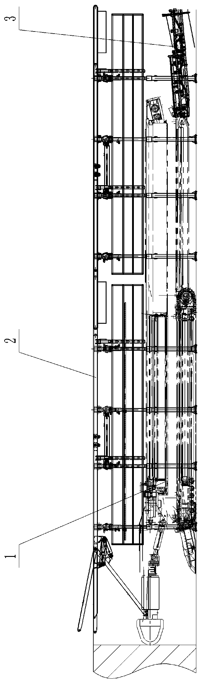
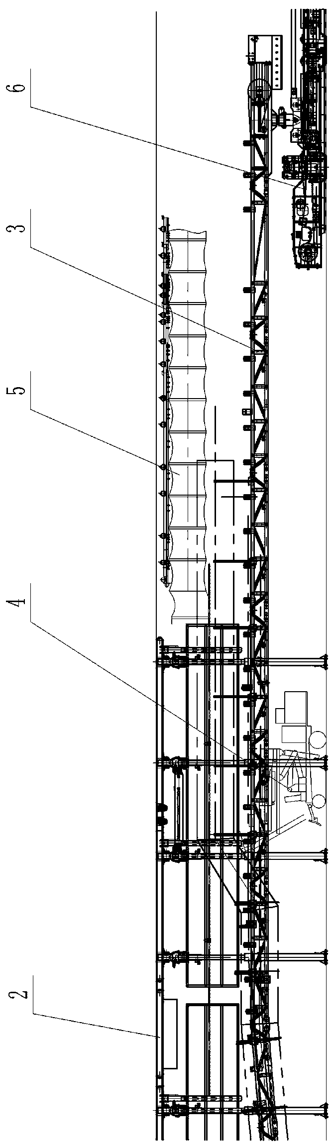
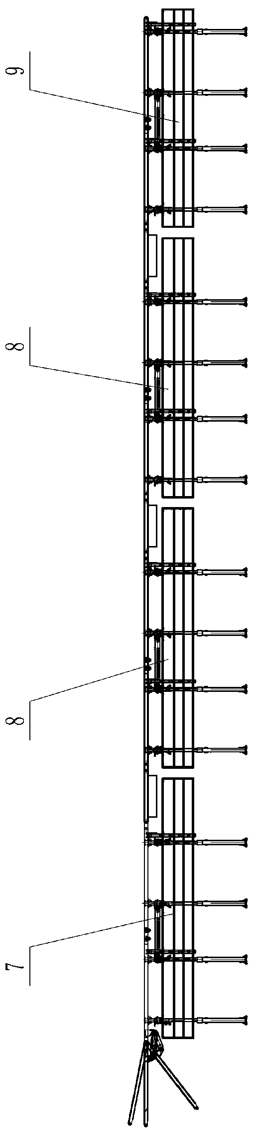
[0033] according to Figure 1-12 The specific steps of the present invention are described in detail. The novel tunneling process includes the following steps:

[0034] Step 1. Arrange the roadheader 1 at the front end of the excavation face of the underground roadway. The rear part of the roadheader 1 is connected with the front belt frame of the bridge type conveyor belt conveyor 3, and the rear belt frame of the bridge type conveyor belt conveyor 3 is connected to the The front end of self-moving belt machine tail 6 slides and links to each other. And, the self-moving belt conveyor tail 6 is also provided with a wet dust removal fan and an emulsion pumping station. Afterwards, an excavation temporary support device 2 that can move forward synchronously with the fully mechanized excavation operation is installed on the outside of the roadheader 1, and then the surrounding rock of the excavation working face of the entire roadheader 1 and the front half of the bridge convey...


PUM


Abstract

The invention provides a novel tunneling process in order to solve the problems that a tunneling machine in the prior art needs to be halted and retreated after tunneling a distance and then conductsnet laying, anchor rod driving operation and other permanent supporting operation, the roadway tunneling efficiency is low and mine excavation is hard to follow. According to the novel tunneling process, a temporary supporting device is separated from the tunneling machine, the tunneling temporary supporting device is independently arranged on the outer portion of the tunneling machine in a covering mode and can move forwards along with tunneling of the tunneling machine to support a roof exposed during tunneling in time. Meanwhile, operation personnel can implement anchor rod driving or shederecting and other permanent supporting operation inside the tunneling temporary supporting device behind the tunneling machine. Through the novel tunneling process, noninterference and parallel operation between tunneling of the tunneling machine and roadway permanent supporting are realized, the operating ratio and tunneling efficiency of the tunneling machine can be improved, the safety of theroadway tunneling operation environment is improved, the labor intensity of net laying and permanent supporting by workers is reduced, and the condition that mine excavation is hard to follow is effectively relieved.

Description

technical field [0001] The invention belongs to the technical field of underground roadway excavation operations, and specifically relates to a method that can improve the operating rate and excavation efficiency of the roadheader, improve the safety of the roadway excavation operation environment, reduce the labor intensity of workers' net laying and permanent support, and can effectively alleviate mine excavation. A new tunneling process that continues the stressful situation. Background technique [0002] Mining operations and tunneling operations are two key links in coal mine production. With the rapid development of technical equipment, the level of fully mechanized mining in my country has been greatly improved, and the mining speed of coal mining faces has also been accelerated. However, the substantial increase in the output of the working face is accompanied by the consumption of a large number of mining roadways, which leads to the problem that the speed of roadwa...

Claims


Application Information

Patent Timeline
Patent Type & Authority Applications(China)
IPC IPC(8): E21D19/04E21D20/00E21D15/44E21D15/50
CPCE21D15/44E21D15/50E21D19/04E21D20/00
Inventor 曹伟宋建军滕飞李志海杨宏光李文武邱洋边俊奇罗福利高晓明范超王旭东王超许磊郭俊生赵艳珍任帅
Owner SHENYANG TIAN AN TECH CO LTD
Why Eureka
Try Eureka