Flexible multilayer frequency selective surface with transmission zero point

A technology of frequency selective surface and transmission zero point, applied in electrical components, antennas and other directions, it can solve the problems of unstable out-of-band selectivity of single-frequency point passband, difficult to meet the needs of equipment with different shapes, and large thickness, etc., to improve the shape The effect of deformation adaptability, improvement of out-of-band selection characteristics, and simple processing technology

Inactive Publication Date: 2019-11-05
XIDIAN UNIV
View PDF3 Cites 13 Cited by
  • Summary
  • Abstract
  • Description
  • Claims
  • Application Information

AI Technical Summary

Problems solved by technology

The traditional frequency selective surface manufacturing technology is to use rigid dielectric substrates to manufacture printed circuit boards (PCBs), which will result in very heavy structures and rigid structures that are difficult to deform with different shapes of application equipment
For example, in 2017, M. Hussein et al. published "A Low-Profile Miniaturized Second-Order Bandpass Frequency Selective Surface" in IEEE Antennas & Wireless Propagation Letters (vol.16, no.99, pp.2791-2794, Aug.2017), In the thesis, the design of the second-order bandpass frequency selective surface is realized by combining three layers of metal and bending and surrounding. This structure overcomes the problems of large size and thickness of the frequency selective surface and has two transmission zeros on the right side of the passband. , which improves the out-of-band selection characteristics, but this frequency selective surface is difficult to apply to many modern applications, such as radome, microwave antenna and electromagnetic shielding, which have high requirements for flexibility, light weight and conformality
In 2016, M.Nauman et al published "A Miniaturized Flexible Frequency Selective Surface for X-Band Applications" in IEEE Transactions on Electromagnetic Compatibility journal (vol.58, no.2, pp.419-428, Feb.2016), the paper The design of the X-band miniaturized flexible frequency selective surface is realized by winding the metal strip to increase the capacitance and inductance. The frequency selective surface FSS is printed on one side of the Rogers / Duroid 5880 flexible laminate to achieve a conformal structure. , while the miniaturization of its size provides good stability for different polarizations and incident angles, but this frequency selective surface FSS is fabricated using laminated sheets with a certain bending curvature, which cannot be recovered or re-formed once formed Bending to other curvatures, i.e. non-recoverable flexibility
On the one hand, most of the frequency selective surfaces designed in the prior art are rigid board structures manufactured by PCB technology, which are difficult to meet the needs of equipment with different shapes; on the other hand, they are mostly single-layer structures with single-frequency Unstable passband and poor out-of-band selectivity affect the use effect

Method used


Image

  • Flexible multilayer frequency selective surface with transmission zero point
  • Flexible multilayer frequency selective surface with transmission zero point
  • Flexible multilayer frequency selective surface with transmission zero point

Examples


Embodiment 1

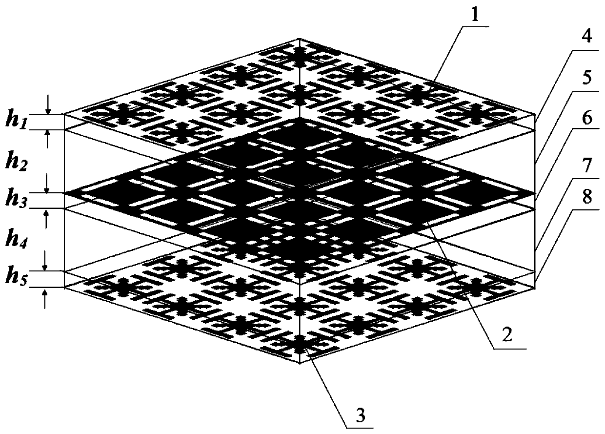
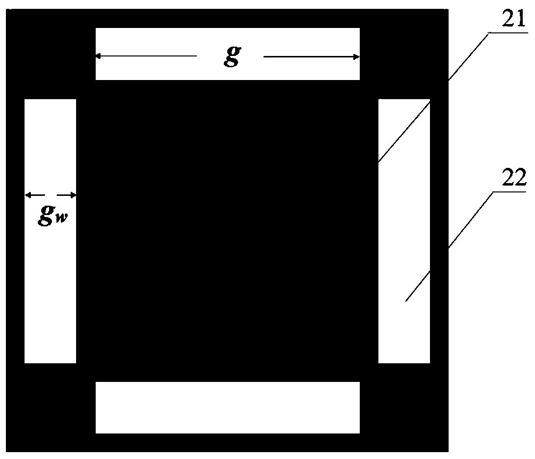
[0036] In this example, the side length p of each unit on the top metal patch resonant layer 1 and the bottom metal patch resonant layer 3 is the same as the side length p of each square unit on the slot coupling metal patch middle layer 2, that is, the side length p=3mm, length g=2mm of rectangular slit 22, wide g w =0.4mm, distance l between two adjacent rectangular slits 22 4 =2mm, the thickness h of the first dielectric substrate 4 1 =0.05mm, the second dielectric substrate 5 thickness h 2 =0.3mm, the thickness h of the third dielectric substrate 6 3 =0.05mm, thickness h of the fourth dielectric substrate 7 4 =0.3mm, the thickness h of the fifth dielectric substrate 8 5 = 0.05 mm.

[0037] In this example, the parameter design of Jerusalem cross 11 and fractal structure 14 is divided into the following two special cases:

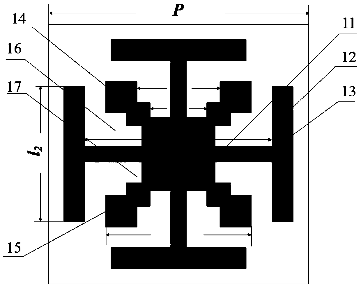
[0038] The rectangular metal strip 12 on top of the cross metal strip in the first case is l 2 =1.9mm, width w 2 =0.2mm, cross metal strip 13 lo...

Embodiment 2

[0042] In this example, the side length p of each unit on the top metal patch resonant layer 1 and the bottom metal patch resonant layer 3 is the same as the side length p of each square unit on the slot coupling metal patch middle layer 2, that is, the side length p=3mm, the length of the rectangular metal strip 12 on the top of the cross metal strip is l 2 = 1.7mm, width w 2 =0.2mm, cross metal strip 13 long l 1 = 2.4mm, width w 1 =0.2mm, the side length l of the square metal patch 15 in the fractal structure 14 3 =1.9mm, the second-level rectangular groove 17 width d 2 =0.7mm, the first level of rectangular groove 16 width d 1 =1.2mm, the thickness h of the first dielectric substrate 4 1 =0.05mm, the second dielectric substrate 5 thickness h 2 =0.3mm, the thickness h of the third dielectric substrate 6 3 =0.05mm, thickness h of the fourth dielectric substrate 7 4 =0.3mm, the thickness h of the fifth dielectric substrate 8 5 = 0.05 mm.

[0043] In this example, the...

Embodiment 3

[0048] In this example, the side length p of each unit on the top metal patch resonant layer 1 and the bottom metal patch resonant layer 3 is the same as the side length p of each square unit on the slot coupling metal patch middle layer 2, that is, the side length p=3mm, cross metal strip 13 long l 1 =2.2mm, width w 1 =0.15mm, the length of the rectangular metal strip 12 on the top of the cross metal strip is l 2 = 1.5mm, width w 2 =0.2mm, the side length l of the square metal patch 15 in the fractal structure 14 3 =1.8mm, the first level of rectangular groove 16 wide d 1 =1mm, the width of the second-level rectangular groove 17 is d 2 =0.6mm, rectangular slit 22 length g=1.7mm, width g w =0.4mm, distance l between two adjacent rectangular slits 22 4 =2mm, the thickness h of the first dielectric substrate 4 1 =0.05mm, relative permittivity εr1 =3.5, the thickness h of the second dielectric substrate 5 2 =0.3mm, relative permittivity ε r2 =3.5, the thickness h of the ...


PUM


Abstract

The invention relates to a flexible multilayer frequency selective surface with a transmission zero point. The invention mainly solves problems that an existing frequency selective surface is large inweight, poor in appearance adaptability and poor in out-of-band selectivity. The surface comprises a top metal patch resonance layer (1), a slotted coupling metal patch middle layer (2) and a bottommetal patch resonance layer (3), wherein each of the top metal patch resonance layer and the bottom metal patch resonance layer is composed of a plurality of Jerusalem cross shapes (11) and fractal shapes (14); the slotted coupling metal patch middle layer is composed of a plurality of square metal surfaces (21), wherein rectangular gaps (22) are formed in the four edges of the slotted coupling metal patch middle layer; two kinds of media (4 and 5) are arranged between the top metal patch resonance layer and the slotted coupling metal patch middle layer, and three kinds of media (6, 7 and 8) are arranged between the slotted coupling metal patch middle layer and the bottom metal patch resonance layer. The surface provided by the invention is high in surface appearance adaptability, good inout-of-band selectivity, light in structure and capable of being used for radomes and electromagnetic shielding.

Description

technical field [0001] The invention belongs to the technical field of antenna stealth, and mainly relates to a frequency selective surface, which can be used for radome and electromagnetic shielding. Background technique [0002] Frequency selective surface FSS is a two-dimensional periodic structure formed by the arrangement of aperture units on metal patches or metal screens, and can be regarded as a generalized spatial filter with band-stop or band-pass characteristics. The frequency selective surface has the characteristics of frequency selection and polarization selection for electromagnetic waves, and can effectively control the transmission and reflection of electromagnetic waves. In the past few years, frequency-selective surfaces (FSSs) have been extensively studied for various applications ranging from radomes, electromagnetic shielding for microwaves, to circuit-simulating absorbers, reflectors, high-impedance surfaces, and electromagnetic bandgap resonators. Du...

Claims


Application Information

Patent Timeline
Patent Type & Authority Applications(China)
IPC IPC(8): H01Q15/00
CPCH01Q15/0026H01Q15/0093
Inventor 吴边李慧玲宋蕾赵雨桐王跃霖
Owner XIDIAN UNIV
Why Eureka
Try Eureka