Supercharge Your Innovation With Domain-Expert AI Agents!

Conveyor belt

A technology of rubber layer and canvas, which is applied in the field of conveying belts, can solve the problems of surface pollution or modification, and achieve the effect of excellent non-adhesion

Inactive Publication Date: 2019-11-05
BANDO CHEM IND LTD
View PDF8 Cites 0 Cited by
  • Summary
  • Abstract
  • Description
  • Claims
  • Application Information

AI Technical Summary

Problems solved by technology

In the conveying belt made of polycarbonate-based polyurethane, when conveying a moisture-rich and sticky object such as bread dough, confectionary dough, and rice, the surface of the conveying belt including the resin layer will be damaged. Undesirable conditions such as contamination or modification

Method used


Image

  • Conveyor belt
  • Conveyor belt
  • Conveyor belt

Examples


no. 1 approach >

[0023] [carrying belt]

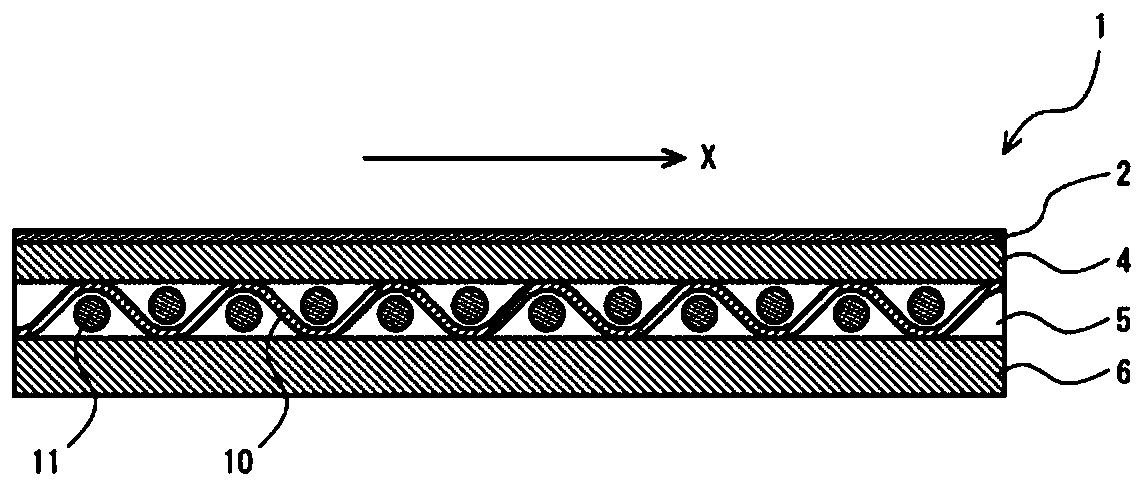
[0024] figure 1 It is a schematic sectional view of the conveyance belt 1 which concerns on 1st Embodiment of this invention. The conveying belt 1 uses a canvas 5 as a core body. The conveyance belt 1 includes a canvas 5 , a first rubber layer 4 laminated on one surface of the canvas 5 , and a cover layer 2 laminated on the surface of the first rubber layer 4 opposite to the canvas 5 . In the said conveyance belt 1, the cover layer 2 becomes an outermost layer. Furthermore, the second rubber layer 6 is laminated on the surface of the canvas 5 opposite to the first rubber layer 4 .

[0025] The conveyance belt 1 is rotated in conjunction with pulleys by a drive mechanism not shown so that the coating layer 2 is on the outside. Therefore, the outer surface of the coating layer 2 becomes the conveyance surface.

[0026] (canvas)

[0027] The conveying belt 1 uses a canvas 5 as a core body. The canvas 5 maintains the tension applied to the conveyanc...

Embodiment approach

[0077] It should be thought that embodiment disclosed this time is an illustration and not restrictive at all points. The scope of the present invention is not limited to the configuration of the above-described embodiments but is shown by the claims, and it is intended that all changes within the meaning and scope equivalent to the claims are included.

Embodiment 1~ Embodiment 6 and comparative example 1~ comparative example 7

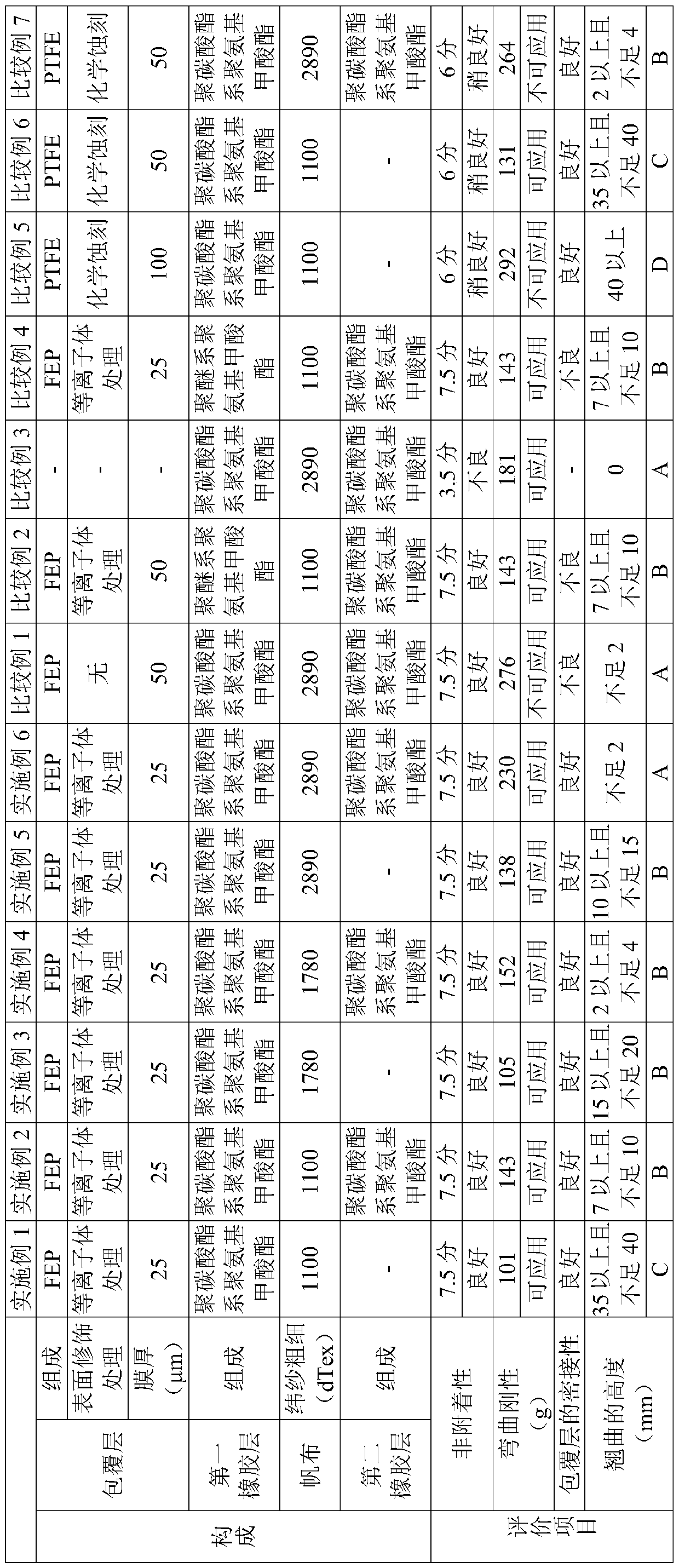
[0081]Regarding Examples 1 to 6 and Comparative Examples 1 to 7, the resins for forming the cover layer shown in Table 1 and polyurethane for forming the first rubber layer and the second rubber layer were produced as materials. carrying belt. In Example 1 to Example 6 and Comparative Examples 1 to 7, a conveyor belt was produced based on the manufacturing method of the above-mentioned conveyor belt. First, by extrusion lamination, polyurethane as a composition for forming a first rubber layer is melt-extruded into a film and bonded under pressure on a canvas to integrate them to form a substrate for forming a substrate. laminated body. Next, the substrate-forming laminate and the coating layer film mainly composed of a coating layer-forming fluororesin were thermocompression-bonded by drum vulcanization at 155° C., and then cooled. Next, polyurethane, which is a composition for forming a second rubber layer, is melt-extruded into a film form on the surface of the canvas of ...


PUM

PropertyMeasurementUnit
thicknessaaaaaaaaaa

Abstract

The present invention provides a conveyor belt which exhibits excellent non-adhesiveness to an article being conveyed and which can suppress detachment of a coating layer while limiting rigidity. Thisconveyor belt uses canvas as a core material and is provided with: a first rubber layer that is laminated on one surface of the canvas and that comprises mainly a polycarbonate-based polyurethane; and a coating layer that is laminated on the first-rubber-layer surface which is opposite the canvas and that comprises mainly a tetrafluoroethylene-hexafluoropropylene copolymer. The coating layer hassurface modification groups at the surface that is bonded to the first rubber layer. The average thickness of the coating layer is preferably 50 [mu]m or less. The surface modification groups are preferably hydroxyl groups, carbonyl groups, carboxyl groups, amino groups, amido groups or combinations thereof. A second rubber layer is also provided on the canvas surface that is opposite the first rubber layer, and the second rubber layer should comprise mainly a thermoplastic polyurethane.

Description

technical field [0001] The invention relates to a carrying belt. Background technique [0002] The conveyance belt is widely used to convey raw materials such as luxury goods, intermediate products, and finished products, and generally includes a laminated body including a resin layer and a canvas layer. As a material for the resin layer, polycarbonate-based polyurethane excellent in strength and abrasion resistance is generally used. In the conveyor belt made of polycarbonate-based polyurethane, when conveying moisture-rich and sticky objects such as bread dough, confectionary dough, and rice, the surface of the conveyor belt including the resin layer will be damaged. Undesirable conditions such as contamination or modification. Therefore, conventionally, for example, there has been disclosed a conveyance belt in which non-adhesion of conveyed objects is improved by coating polytetrafluoroethylene (PTFE) as a fluororesin layer (see Japanese Patent Laid-Open No. 2013-28059...

Claims


Application Information

Patent Timeline
Patent Type & Authority Applications(China)
IPC IPC(8): B65G15/34B32B25/10B32B27/30B32B27/40
CPCB32B25/10B32B27/30B32B27/40B65G15/34
Inventor 竹原洋平
Owner BANDO CHEM IND LTD
Features
  • R&D
  • Intellectual Property
  • Life Sciences
  • Materials
  • Tech Scout
  • Unparalleled Data Quality
  • Higher Quality Content
  • 60% Fewer Hallucinations
Learn More