Low-altitude barrier avoidance method of unmanned aerial vehicle based on ultrasonic waves and binocular vision

A technology of binocular vision and unmanned aerial vehicles, applied in the direction of sound wave reradiation, radio wave measurement system, measurement device, etc., can solve the problems of inaccuracy of single ultrasonic wave and binocular vision

Pending Publication Date: 2019-11-08
TAIZHOU UNIV
0 Cites 9 Cited by

AI-Extracted Technical Summary

Problems solved by technology

[0004] The technical problem solved by the present invention is judging whether to avoid obstacles when the UAV encounters an obstacle, ignoring the problem of the UAV’s own tilt, the critical problem of equal division of the viewing angle, the problem of threshold calculation, and ...

Abstract

The invention provides a low-altitude barrier avoidance method of an unmanned aerial vehicle based on ultrasonic waves and binocular vision. The method comprises the following steps that starting of abinocular camera and emission of eight-way ultrasonic waves are conducted synchronously; the binocular camera acquires an image in front of the unmanned aerial vehicle, if a barrier in front of the unmanned aerial vehicle is not detected, the binocular camera continues to collect images, if a barrier exists in front of the unmanned aerial vehicle, a depth value of the barrier is acquired by utilizing a disparity map; the real perpendicular distance and horizontal distance of the barrier are acquired according to the attitude compensation pitch angle and roll angle of the unmanned aerial vehicle; whether or not a threshold value is exceeded is judged, and a corresponding barrier avoidance mode is selected according to specific information of the barrier; once the eight-way ultrasonic wavesdetect the barrier, corresponding binocular vision is started for detecting the barrier, and then selective barrier avoidance is conducted according to the above steps. By means of the provided barrier avoidance method, whether or not barrier avoidance is needed is quickly judged, specific positions of the barriers are quickly judged, the interference of the ground and walls can also be avoided,and accurate barrier avoidance of the unmanned aerial vehicle is achieved.

Application Domain

Attitude controlAcoustic wave reradiation

Technology Topic

Rolling angleLow altitude +8

Image

  • Low-altitude barrier avoidance method of unmanned aerial vehicle based on ultrasonic waves and binocular vision
  • Low-altitude barrier avoidance method of unmanned aerial vehicle based on ultrasonic waves and binocular vision
  • Low-altitude barrier avoidance method of unmanned aerial vehicle based on ultrasonic waves and binocular vision

Examples

  • Experimental program(1)

Example Embodiment

[0051] specific implementation plan
[0052] In order to make the purpose, technical solution and advantages of the present invention clearer, the following in conjunction with the attached Figure 1-9 , to further describe the present invention in detail.
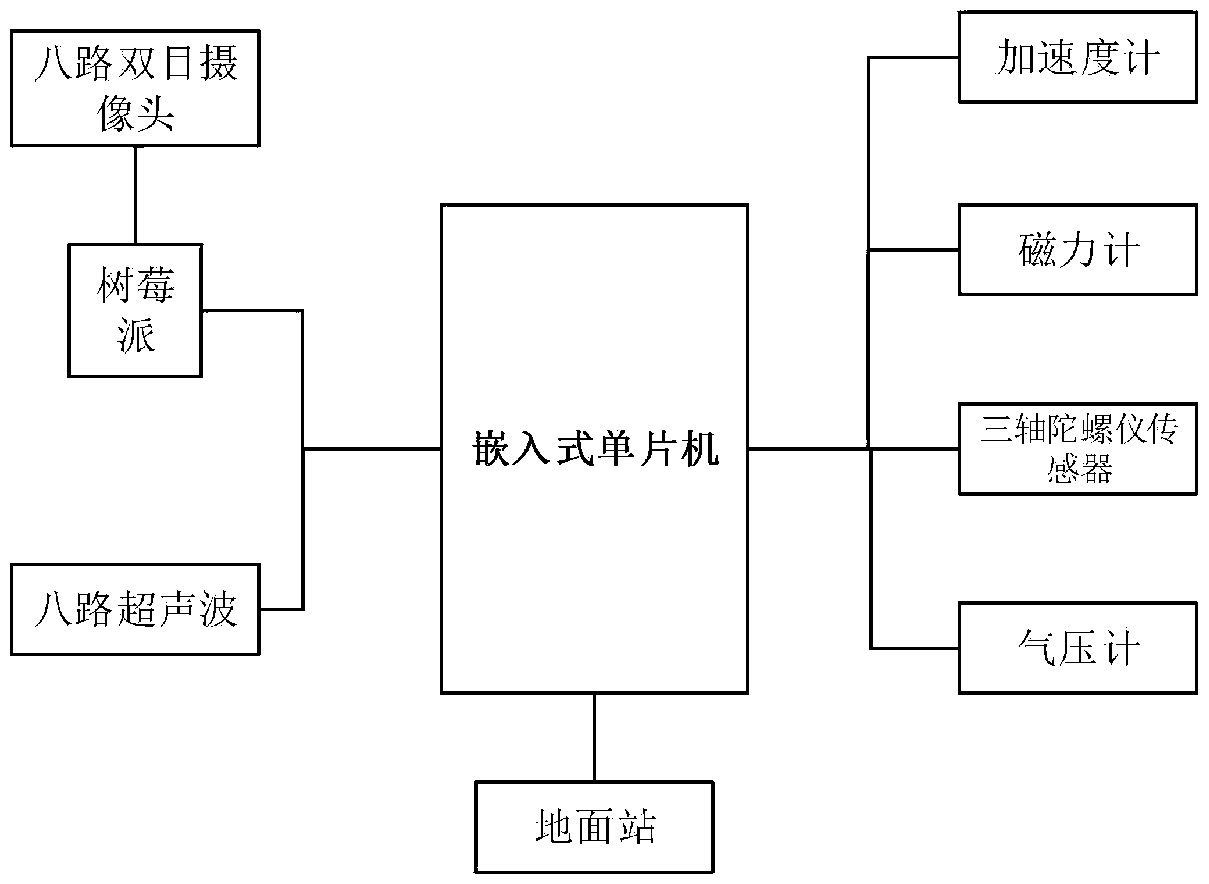
[0053] like figure 1 As shown, the present invention is a UAV low-altitude obstacle avoidance method based on ultrasonic waves and binocular vision. The UAV low-altitude obstacle avoidance system includes a UAV attitude recognition module, a flight control module, an eight-way binocular camera module and Eight-channel ultrasonic module. The attitude recognition module includes an accelerometer, a gyroscope, a magnetometer and a barometer, which are used to obtain the attitude angle (pitch angle, roll angle and yaw angle) and height of the drone itself. The flight control module is mainly an embedded single-chip microcomputer and a ground station, which control the flight attitude of the drone.
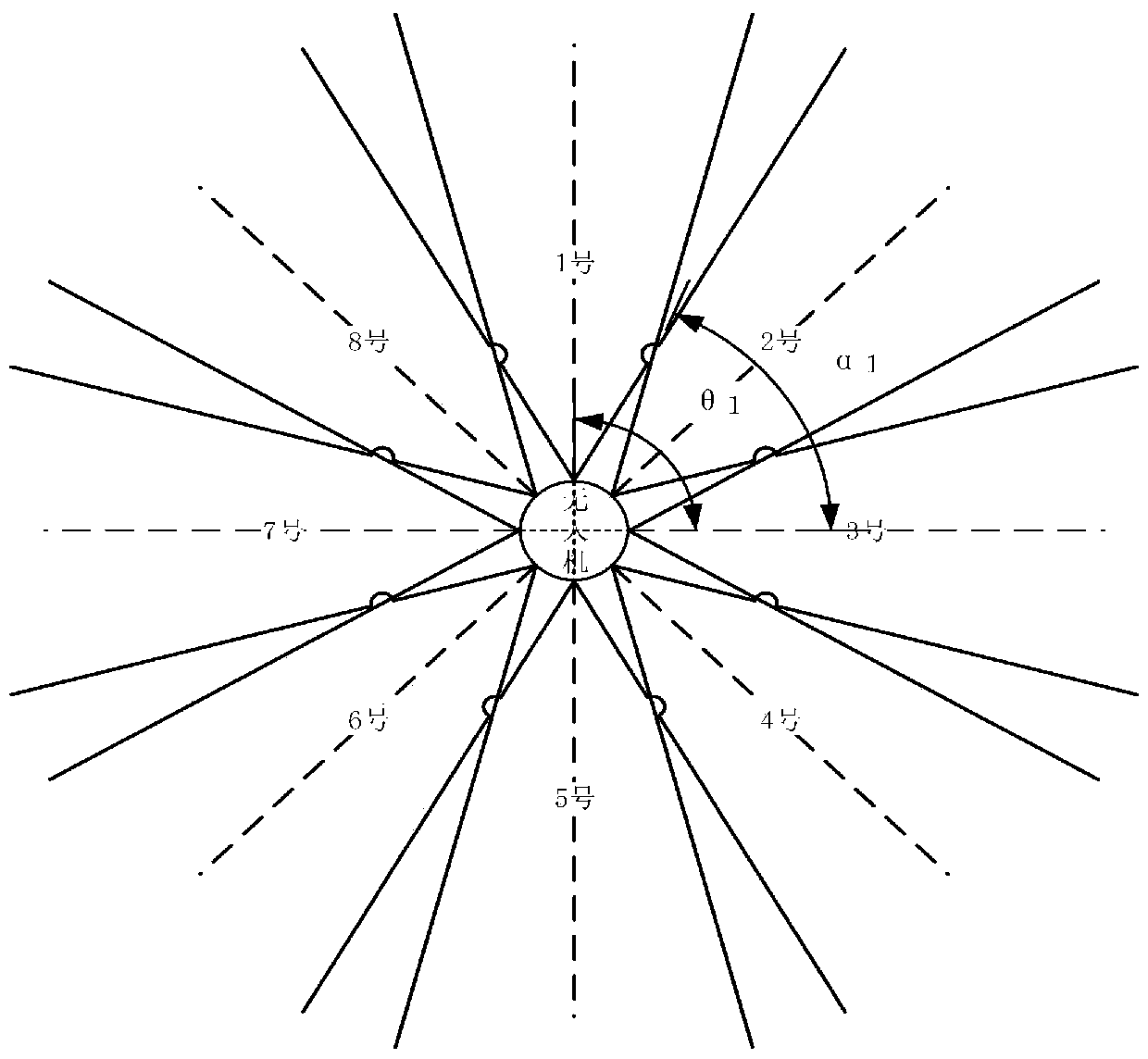
[0054] like figure 2 As shown, the eight-way binocular camera module includes eight binocular cameras and one Raspberry Pi, which is used to realize 360-degree binocular vision obstacle avoidance without dead angle. The eight-way binocular vision module is evenly arranged around the drone, and the eight binocular vision modules are placed in front of the drone, front left, left, back left, back, back right, right, and front right every 45 degrees. orientation. Described raspberry group is the processing system of binocular camera, connects binocular camera by USB, is used for processing the depth value of disparity map, judges whether to avoid obstacle, connects flight controller by IO port, controls the flight attitude of unmanned aerial vehicle;
[0055] The eight-way ultrasonic module is evenly arranged directly below the eight-way binocular vision module, and the eight ultrasonic waves are placed in front of the drone, front left, left, back left, back, back right, right, and front right every 45 degrees. Eight directions.
[0056] Further, the eight-way binocular vision and eight-way ultrasonic measurement ranges have overlapping parts, and the central angles of each overlapping part are 22.5°, 67.5°, 112.5°, 157.5°, 202.5°, 247.5°, 292.5°, 337.5°. Re-divide the visual range, the binocular and ultrasonic measurement ranges corresponding to the bit numbers are: No. 1 measurement range; (337.5, 360) and (0, 22.5); No. 2 to No. 8 number measurement range: (-22.5+45*( n-1),22.5+45*(n-1)).
[0057] like image 3 As shown, the UAV low-altitude obstacle avoidance method based on ultrasonic and binocular vision includes the following steps:
[0058] Step 1. Turn on the eight-channel ultrasonic wave, determine the flight direction angle of the drone and turn on the binocular camera in the corresponding area; the flight direction angle of the drone must be determined, as follows:
[0059] ④ It is stipulated that the pitch angle of the UAV flying forward is positive, and the roll angle of the UAV flying to the left is positive. If the UAV only has a pitch angle, the front camera or the rear camera can be selected according to the positive or negative of the pitch angle. .
[0060] ⑤If the UAV only has a roll angle, choose to turn on the left camera or the right camera according to the positive or negative of the roll angle.
[0061] ⑥If the drone has pitch and roll angles, set the pitch angle of the drone to γ, and the roll angle to φ, where the yaw angle λ is at (-π, π), and the pitch angle γ is at The roll angle φ is at The resultant force on the UAV is F, and F=mg at the beginning. like Figure 4 As shown, the change state of the UAV can be regarded as pitching first and then rolling, or vice versa. F corresponds to F in the yz plane y =FCOSφ, then the component of the y-axis is Y=F y Sinγ=FCOSφSinγ, similarly the corresponding xz plane X=FSinφ. Through the component values ​​of the X and Y axes, the angle κ of the y-axis to the x-axis can be calculated:
[0062]
[0063] If κ<0, then κ=κ+360, the calculated κ is in the (0°, 360°) interval, where the positive axis of y is 0°; In the overlapping area (i=1,2,3,...8), the binocular camera in the i-th area is turned on, which is more conducive to autonomous obstacle avoidance;
[0064] Step 2. Obtain the environmental image in front of the drone through the binocular camera. Identify whether there is a target object in front of the drone based on the acquired environmental image; if the target object is identified in front, based on the current attitude information of the drone and the environmental image The acquired depth value of the target object determines whether the target object in front will affect the continued flight of the UAV; calculate the vertical distance between the UAV and the target object and the horizontal distance of the UAV based on the depth value of the target object; If the vertical distance of the target object is lower than or equal to the threshold and the horizontal distance is smaller than the threshold, the UAV takes obstacle avoidance measures; if the vertical distance of the target object identified in front is higher than the threshold, the UAV does not take obstacle avoidance measures and remains The current flight direction continues to fly; the attitude sensor is a three-axis sensor and a three-axis accelerometer, which is used to obtain the pitch angle, roll angle and yaw angle of the drone; the depth value of the target object is obtained through the binocular disparity map;
[0065] Further, the depth value of the target object is obtained by the following method:
[0066] ◆The binocular camera acquires the environmental image in front of the drone, including the first image and the second image;
[0067] ◆The two cameras of the binocular camera obtain the internal and external parameters of the cameras through Zhang's calibration method, and then correct the first image and the second image through the external parameters and distortion coefficients of the cameras;
[0068]◆Use the SGBM algorithm to perform stereo matching on the corrected first image and the second image to obtain the disparity map of the two images;
[0069] ◆ Obtain a depth image based on the disparity map, and extract the depth value of the target object according to the depth image.
[0070] Further, if there is an obstacle in the target object, the distance between the UAV and the obstacle is obtained based on the target depth value; specifically, if the target object is recognized in front, the distance between the UAV and the target object is calculated based on the target object depth value The vertical distance and the horizontal distance of the drone; if the vertical distance of the target object identified in front is lower than or equal to the threshold and the horizontal distance is less than the threshold, the drone takes obstacle avoidance measures; if the vertical distance of the target object identified in front If the value is higher than the threshold, the UAV will not take obstacle avoidance measures and will continue to fly in the current flight direction.
[0071] In this embodiment, in step 2, based on the current attitude information of the UAV and the depth value of the target object acquired according to the environmental image, it is judged whether the target object in front will affect the continued flight of the UAV. The specific method is:
[0072] ③ From the calculated horizontal components of the drone's x-axis and y-axis, calculate the corresponding angle K of the resultant force F projected onto the XY plane:
[0073]
[0074]
[0075] ④In this example, within the pitch angle of the UAV (-30°, 30°), the plane where the UAV body coordinate system is located is the baseline, the angle below the baseline is negative, the angle above is positive, and the field of view angle is in (- 30°, 30°); according to the obtained depth value of the target object, the specific steps for judging whether the target object in front will affect the continued flight of the drone are:
[0076] (5) if Figure 5 As shown, the field of view angle in the vertical direction is equally divided, and the corresponding angle is θ 1 , θ 2 , θ 3 ,....θ n , the depth value x corresponding to the target object is identified from top to bottom within the field of view 1 、x 2 、x 3 、...x n , the angle corresponding to each corresponding angle to the reference line is α 1 、α 2 、α 3 、... α n , α n =30°-θ n;Corresponding calculation angle β 1 , β 2 , β 3 、... β n , β n = α n +K, where 0°
[0077] (6) If all h are calculated from the beginning nThreshold g, it is determined that there is no obstacle ahead, and the UAV continues to fly forward;
[0078] (7) The specific calculation method of the threshold g is as follows: the corresponding angle K of the projected resultant force F to the XY plane is known, and the inclination angle of the flight direction of the unmanned aerial vehicle is 90-K;
[0079] Let the length and width of the UAV approximate to a circle whose diameter is the axis of the UAV, z is the diameter of the circle plus the diameter of the rotor blades, and calculate the change height m corresponding to each camera for each attitude change, and N is according to the above Determine the angle to open the corresponding camera (see Figure 7 and Figure 8 ); According to the above example, the flight direction κ of the UAV can be calculated. When the UAV tilts to the κ direction, there must be an axis perpendicular to the κ direction that remains unchanged when tilting, and the relative angle between the open camera and κ is calculated. , calculate the remaining angle; calculate the distance perpendicular to the invariant axis according to the diameter and the remaining angle of the UAV, and then calculate m according to the inclination angle K. The calculation formula is as follows:
[0080]
[0081] Find the threshold g below the UAV that changes. Gd is the height from the controller to the bottom of the tripod when the UAV does not have any inclination angle. In this example, it is 20cm. The relationship between calculating gd and the inclination angle of the UAV is:
[0082] gd*cos(90-K)
[0083] Therefore, if the UAV has a tilt angle, the threshold for changing is:
[0084] g=gd+m
[0085] (8) Calculate the vertical component h corresponding to each depth value from top to bottom 1 =x 1 *|cosβ 1 |, h 2 =x 2 *|cosβ 2 |, h 3 =x 3 *|cosβ 3 |... h n =x n *|cosβ n |, respectively calculate the mutation threshold S 2 =h 2 -h 1 , S 3 =h 3 -h 2 , S 4 =h 4 -h 3 、...S n =h n -h n-1 , if S n20cm means that the vertical distance changes abruptly, and you will encounter such Figure 5 case, the specific solution is as follows:
[0086] 3) When S n20cm, calculate the distance L between the obstacle and the drone n =x n *sinβ n , get h from the above angle n-1 corresponding angle a n-1 = θ n-1 +γ-30°, then find the corresponding h c =L n *tan(a n-1 ); if h c
[0087] 4) If all h are calculated from the beginning n30cm, it is determined that there is no obstacle ahead, and the drone continues to fly forward;
[0088] Further, the distance L between the obstacle and the UAV n =x n *sinβ n , average the horizontal distance measured n times to reduce the measured error; the horizontal direction is equally divided according to the image width, and the equal division interval is set to τ. According to the change of the camera coordinate system, the image coordinates are converted to actual coordinates. x, y are image coordinates, x c ,y c ,z c is the actual coordinate, f is the focal length of the camera. then the same bit z c The image disparity of the obstacle: Then τ=Δx, to find the actual horizontal potential difference: The vertical line of the horizontal division is regarded as the intersection line of the camera plane rotated by o degrees of the binocular camera and the original camera plane. like Figure 9 As shown, the angle of rotation can be calculated Calculate the real distance Lz from the target point to the original image plane when there is only pitch or roll:
[0089]
[0090] Among them, l n Indicates the corresponding depth value after rotation.
[0091] When both pitch and roll exist, it can be decomposed into pitching and rolling first, and now pitching to calculate the real distance L after pitch angle compensation n , the roll is equivalent to turning the real distance by the roll angle (see Figure 7 ), the specific compensation method is: R n It is the distance measured by different horizontal divisions of the binoculars when there is pitch and roll, LX n Compensate the distance of the y-axis for the pitch angle. L 补偿 It is the distance after pitch and roll compensation. When L n = R n *|sino|cosδ, LX n = R n When |coso|, there is
[0092]
[0093] Step 3. Always turn on the eight-channel ultrasonic wave during the flight of the drone to prevent obstacles from suddenly appearing in the dead zone of detection. When the ultrasonic wave detects an obstacle, judge where the obstacle is. If the judged obstacle is different from the flight direction, turn on The binocular vision at the corresponding position detects whether obstacle avoidance is required, and repeats the obstacle avoidance method in step 2;
[0094] Further, if the obstacle judged by ultrasound is in the same direction as the flight, then L n Compared with the set threshold, if L n is greater than the set threshold, the UAV will fly forward, if Ln If the value is less than the set threshold, the UAV chooses to avoid obstacles. Specifically, L n When it is less than 15m and greater than 10m, it enters the first safe distance, and the UAV adjusts the flight tilt angle to reduce the speed appropriately; L n When it is less than 10m and greater than 5m, it enters the second safe distance, and the drone’s alarm light flashes to slow down and brake; L n When it is less than 5m into the dangerous distance, the drone brakes urgently and returns to 5m. If the obstacle judged by ultrasound is different from the flight direction, then L n Compared with the set threshold, if L n is greater than the set threshold, the UAV will not avoid obstacles, if L n If it is less than the set threshold, the UAV will fly upward until there is no obstacle to stop the upward flight, and the UAV will stop hovering.
[0095] The specific embodiments described above have further described the purpose, technical solutions and beneficial effects of the present invention in detail. It should be understood that the above descriptions are only specific embodiments of the present invention and are not intended to limit the present invention. Any modifications, equivalent replacements, improvements, etc. made within the spirit and principles of the present invention shall be included within the protection scope of the present invention.

PUM

no PUM

Description & Claims & Application Information

We can also present the details of the Description, Claims and Application information to help users get a comprehensive understanding of the technical details of the patent, such as background art, summary of invention, brief description of drawings, description of embodiments, and other original content. On the other hand, users can also determine the specific scope of protection of the technology through the list of claims; as well as understand the changes in the life cycle of the technology with the presentation of the patent timeline. Login to view more.
Why Eureka
Try Eureka